Single Module UPS Installation
12
X3 Ancillary Control and Alarms
X3 IN DRY: Environmental, Battery Ground Fault and Generator Contacts
The UPS accepts external signalling from voltage-free (dry) contacts connected to finger-proof, push-in ter-
minal X3 IN DRY. Subject to prior software programming, the signalling is accepted by the UPS when
connection between the relevant terminal and the +12V terminal is altered. Cables connected to X3 IN
DRY must be segregated from power circuits (for screening purposes), double insulated and of a typical 0.5
to 1mm
2
cross-section area for maximum runs between 25 and 50 meters (82-164 ft), respectively.
1.8.2 Maintenance Bypass Cabinet Interface
J26 and J30 are the MBC interface.
1.8.3 External Circuit-Breaker Interface
J10 is the interface to any external battery circuit breaker (BCB).
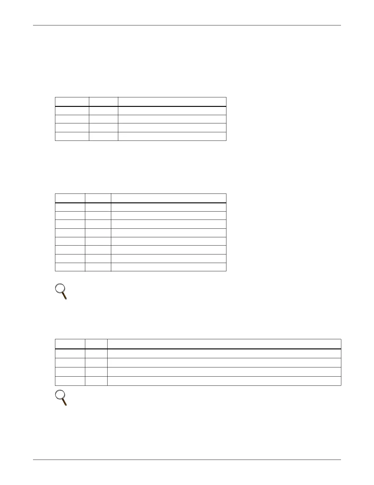
Table 3 Input dry contacts at X3
Position
Name
Description
J4.1 ENV
3
Battery Room Alarm (NC)
J4.2 BtG Battery Ground Fault Detection (NC)
J4.3 GEN
1,2
On Generator (NO)
J4.4 +12V +12V Power
1 - Must be configured by configuration software before becoming active.
2 - When activated, the charger current can be limited, via software, to a percentage of the full charger current (0-100%).
3 - Activating this feature turns the battery charger off.
Table 4 Maintenance bypass cabinet interface
Position
Name
Description
J26.1 T_IT
1
Input transformer overtemperature (NC)
J26.2 AUX_I Reserved
J26.3 +12V +12V Power
J26.4 GND Power Ground
J30.1 FUSE Reserved
J30.2 F_FAN Fan Fail Alarm (NC)
J30.3 T_OT
1
Output Transformer Overtemperature (NC)
J30.4 AUX_O Reserved
1
- Must be configured by software before becoming active
NOTE
All auxiliary cables of terminal must be double-insulated. Wire should be 0.5-1.5mm
2
(16-20AWG) stranded for maximum runs between 25 and 50 meters (82-164ft.) respectively.
Table 5
External circuit-breaker interface
Position
Name
Description
J10.1 DRV BCB Driver Signal - (reserved)
J10.2 FB BCB Contact State -(reserved)
J10.3 GND Power Ground
J10.4 OL BCB On-Line - Input - This pin will become active when BCB interface is connected. (N.O.)
NOTE
All auxiliary cables of terminal must be double-insulated. Wire should be 0.5-1.5mm
2
(16-20AWG) stranded for maximum runs between 25 and 50 meters (82-164ft.) respectively.
 Loading...