Installation Drawings
33
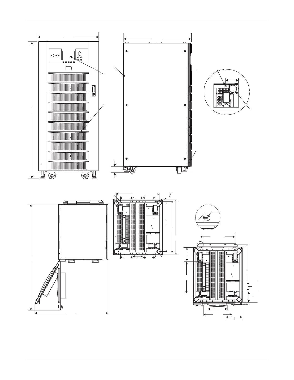
Figure 22 General arrangement—10-20kVA UPS module
1253
885
3
R6
A
A
8-M10
519.6
572
706
235
345
167
611
150
150
650
150
150
120
4-O50
405
142.5
415.2
138.25
111.8
FRONT VIEW
LEFT SIDE VIEW
Leveling feet
Detail A, rear of unit
shown without side panel
Levele
10mm dia threaded
mounting holes
86.5
7
2
1
700
600
1400
90
1) Air inlet grille
2) Air outlet grille
3) Adjustable fixing feet
4) Castors for maneuvering
5) Seismic anchors (option)
6) Cable entry
7) Operator control and display panel
All dimensions are in mm.
 Loading...