MAS2600: Maintenance and Troubleshooting Reference Manual
August 2023 RM 6000-01-001-24
49
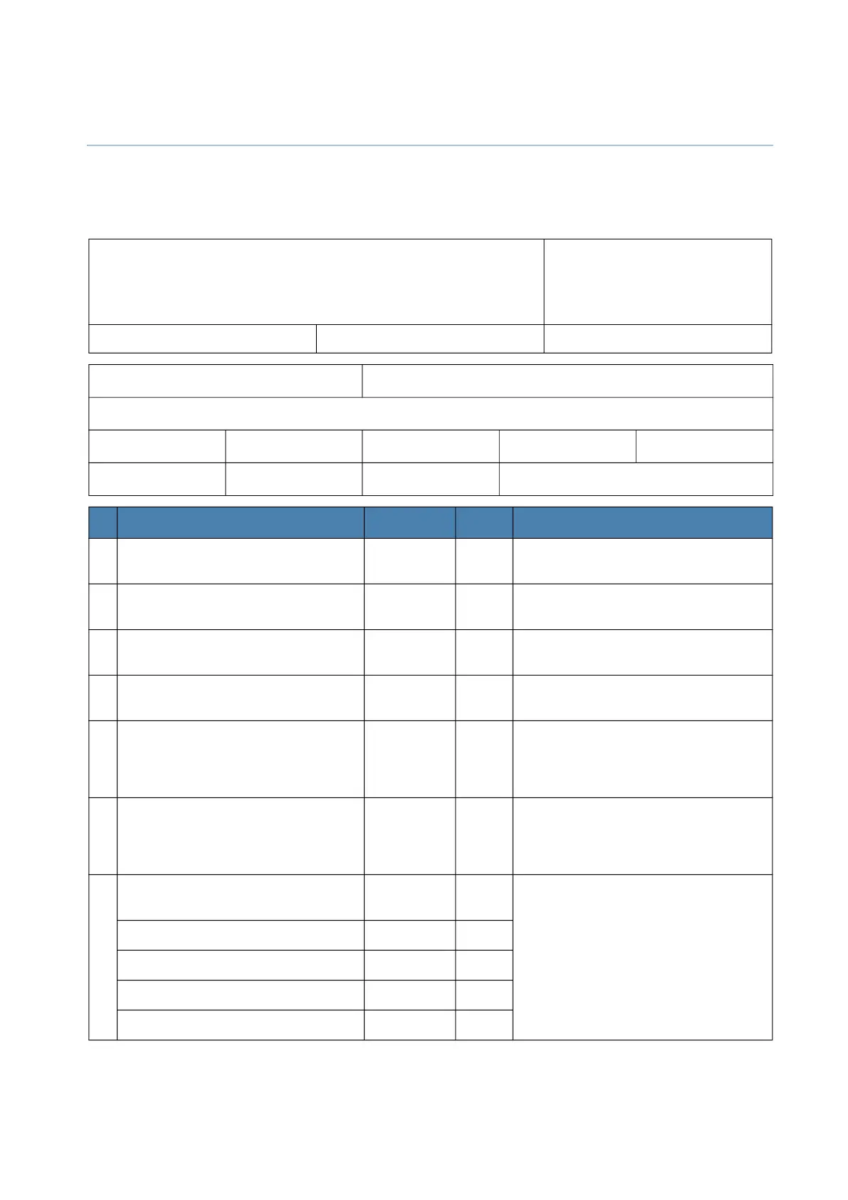
MAS 2600 Test Sheet
Name
ATT.
Emerson
Marine Solutions
Damcos A/S, Service Department
FAX.: +45 5578 7272
Ship name Yard NB no.
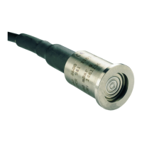
MAS 2600 Transducer serial no. MAS 2600 Amplifier serial no.
Tank name
Liquid in tank HFO DO Ballast Other
The tank is Full Empty Other
Step Result Unit Limits
1 Measure voltage between terminal 5
and 6.
V DC Voltage should be in the range 17 to 22 V
DC. Check power supply.
2 Measure nipple voltage between
terminal 5 and 6.
V AC Voltage must not exceed 2 V AC.
Check power supply.
3 Measure sensor excitation voltage
between terminal 7 and 10.
V DC Voltage should be in the range 3.0 and
6.2 V DC.
4 Measure sensor excitation voltage
between terminal 8 and 9.
mV DC Voltage should be in the range -15 to 100
mV DC.
5 Measure current in supply lead to
terminal 5.
mA DC Current should be in the range 4 to 20
mA and the same value as measured in
point 6. if not the amplifier may be
defect.
6 Measure current in supply lead to
terminal 6.
mA DC Current should be in the range 4 to 20
mA and the same value as measured in
point 5. if not the amplifier may be
defect.
7 Measure sensor resistance with sensor
cable unconnected between:
If the measured resistance is less than 1
M Ohm the sensor is considered defect.
Terminal 7 to cable shield. M Ohm
Terminal 8 to cable shield. M Ohm
Terminal 9 to cable shield. M Ohm
Terminal 10 to cable shield. M Ohm
 Loading...


