 Loading...
Do you have a question about the Emerson Rosemount 520 and is the answer not in the manual?
| Brand | Emerson |
|---|---|
| Model | Rosemount 520 |
| Category | Transmitter |
| Language | English |
Explains HART Protocol advantages for digital communication over analog wiring, simplifying configuration, calibration, and maintenance.
Lists tools like Field Communicator and HART modems for configuring the transmitter, enabling remote diagnostics and maintenance.
Advises confirming HART capability of systems for communication with HART Revision 7 Protocol before installation.
Emphasizes verifying the latest device driver (DD/DTM) is loaded for proper communication with the transmitter.
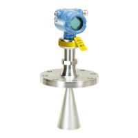
Details the steps for internal mounting of the transmitter to the tank wall using a bracket and spring.
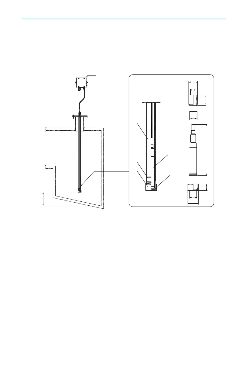
Explains the procedure for pole mounting the transmitter inside a tank pipe using a deck socket, nut, and gasket.
Describes the installation of the transmitter via a nipple pipe to a tank wall or ball valve using a nut and gasket.
Outlines the process for flange mounting the transmitter to the tank wall using a flange, nut, and gasket.
Details mounting the transmitter using a flange and ball valve, secured by a nut and gasket.
Explains mounting the transmitter and flange using a rubber tube secured by clips and a deck socket.
Describes securing the transmitter to a PTFE tube using a nut and ferrule, then attaching to a flange.
Specifies using shielded twisted pair cable and provides a table for maximum signal cable lengths based on transmitter cable length.
States that the vent tube must be directed to an area with atmospheric pressure for accurate readings.
Mentions power supply and load limitations are described in Figure 8, and resistance of safety barriers must be included.
Presents point-to-point and multidrop wiring diagrams for connecting the transmitter, including HART communication requirements.
Guides on verifying transmitter configuration using a Field Communicator, requiring installation of the latest Device Driver (DD).
Details performing a zero trim using a Field Communicator by connecting it and inputting a specific fast key sequence.
States that the EU Declaration of Conformity can be found at the end of the guide or on Emerson.com/Rosemount.
Covers ATEX Intrinsic Safety certification details, including certificate number, standards, markings, and special conditions for safe use.
Presents IECEx Intrinsic Safety certification information, including certificate, standards, markings, and input parameters.
Lists additional type approvals from ABS, Bureau Veritas (BV), Lloyd's Register (LR), and DNVGL for marine and offshore applications.