5 Wire and apply power
5.1 Wire the transmitter
Wiring diagrams are located inside the terminal block cover.
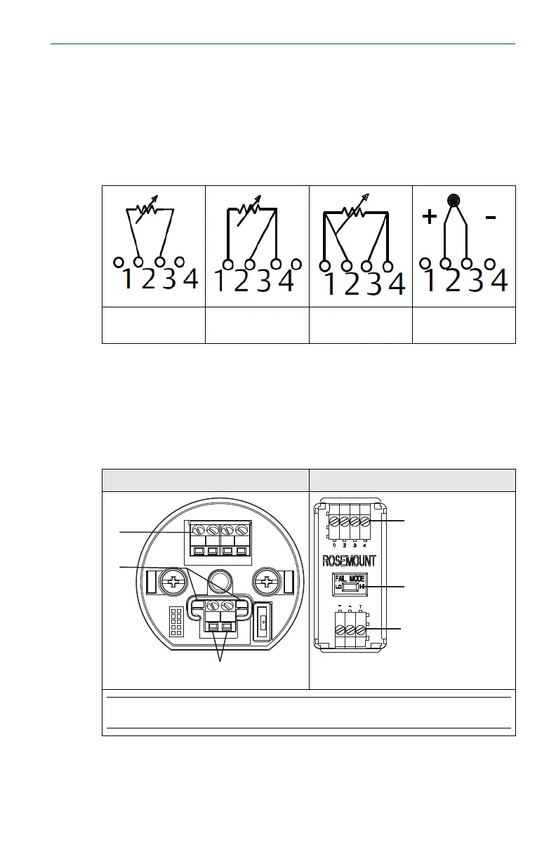
Table 5-1: Sensor Connections Diagram
2-wire RTD and V 3-wire RTD and
V
(1)
4-wire RTD and V T/C and mV
(2)
(1)
Rosemount
™
provides 4-wire sensors for all single element RTDs. Use these RTDs
in 3-wire configurations by leaving the unneeded leads disconnected and
insulated with electrical tape.
(2) The transmitters must be configured for at least a 3-wire RTD in order to
recognize an RTD with a compensation loop.
5.2 Power the transmitter
Rosemount 644H Rosemount 644R
Note
Max torque is 6 in-lbs. (0.7 N-m)
A. Sensor terminals
B. Communication terminals
April 2019 Quick Start Guide
Quick Start Guide 19
 Loading...