 Loading...
Do you have a question about the Emerson Rosemount 644R and is the answer not in the manual?
| Type | Temperature Transmitter |
|---|---|
| Measurement Type | Temperature |
| HART Protocol | HART 7 |
| Display | Optional LCD |
| Input | RTD, Thermocouple, Ohms, mV |
| Sensor Type | RTD, Thermocouple |
| Output | 4-20 mA HART |
| Power Supply | 10.5 to 42 VDC |
| Temperature Range | -40 to 85 °C |
| Process Temperature Range | -40°C to 85°C (-40°F to 185°F) |
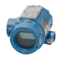
| Enclosure | Aluminum |
| Enclosure Rating | IP66 |
| Mounting | Field |
| Stability | ±0.1% of URL per year |
Essential safety guidelines, notices, and warnings for installation and operation.
Critical safety warning regarding electrical hazards and contact with live terminals.
Procedure for updating software and connecting for bench calibration.
Using the field communicator traditional interface and fast key sequences.
Procedure for entering Callendar Van-Dusen constants via traditional interface.
Procedure for entering Callendar Van-Dusen constants via device dashboard.
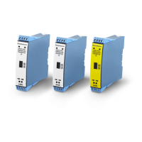
Instructions for setting switches on different Rosemount 644 models.
Step-by-step guide for installing the connection head and transmitter.
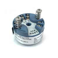
Procedure for mounting the transmitter with a universal head.
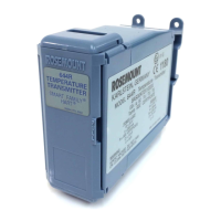
Instructions for mounting rail mount transmitters with threaded sensors.
Diagrams and instructions for connecting sensors to the transmitter.
Procedures and notes for applying power to the transmitter.
Information on transmitter power requirements and voltage limits.
Procedures for grounding the transmitter based on input types.
Steps to perform analog loop tests via traditional interface and device dashboard.
Details on EU Declaration of Conformity and its availability.
USA explosionproof, intrinsic safety, and non-incendive certification details.
Information on Canadian intrinsic safety and explosionproof certifications.
Details on ATEX and IECEx flameproof, intrinsic safety, and type n certifications.
Certifications for Brazil, China, EAC, and Japan.
Type approvals from ABS, BV, DNV, and LR.
Tables detailing process temperature limits and entity parameters.