DATE :
01/06/2023
SHEET:
1 of 1
SCALE:
NTS@A4
DRAWING No:
EN-IQ8-1PHN
DRAWING Name:
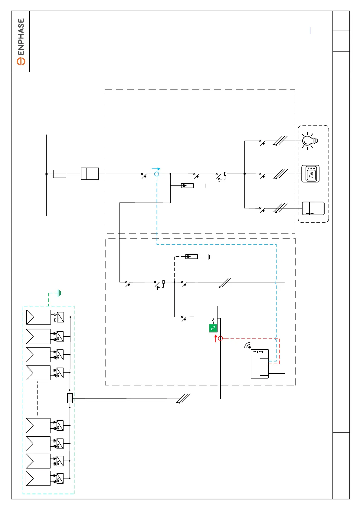
Electrical diagram example: Single-phase IQ8 Series Microinverters grid tied PV system
Q1
1PH+N
Q2
1PH+N
Qn
1PH+N
Consumption measurement
CTs installed on Line
Conductor
AC cable 3 Core
(L1, N, PE)
6 mm² Minimum recommended
conductor size, see note 4
~ ~ ~~~ ~~
AC cable 2x 2.5mm² (L1, N)
IQ Relay
1PH
~
JB
MCB
1PH+N
20 A
MCB
1PH+N
6 A
Main breaker
1PH+N
PV Sub panel Main Panel
RCD - Consumption
1PH+N
See note 8
MCB - Consumption
1PH+N
MCB - Production
1PH+N
40 A
RCD - Production
1PH+N
40 A, 30 mA
See note 8
Production measurement
CT installed on Line
Conductor
Recommended maximum 8
microinverters per IQ Cable section (To
reduce Vrise in cable to <1%)
Single-phase IQ Cable 2x 2.5 mm²
(L1, N)
Array structure
earthing where
required
See note 6
NOTES:
1.These schematics are examples
only. These schematics provide
recommendations to assist the
system designer and installer.
2.The design and installation of
the photovoltaic power plant must
be carried out in accordance with
local electrical standards in the
country of installation and must be
carried out by competent
personnel.
3.Before installing any PV
equipment, check the phase-to-
neutral voltage at the point of
connection. The operating voltage
must be within a range acceptable
for the 230 V microinverters.
4.When planning the system, you
must select the appropriate AC
conductor size to minimize voltage
rise. Select the correct conductor
size based on the distance from
the junction with the microinverter
AC branch circuit to the circuit
breaker in the electrical panel.
Enphase recommends a voltage
rise total of less than 2% from the
start of IQ Cable to the point of
supply. .
5.The 2.5 mm² IQ Cable is usually
protected by a 20 A B curve circuit
breaker.
6. The equipotential bonding
between PV module frames, array
mounting structure and the metal
microinverter mounting brackets
must be installed in accordance
with local electrical standards..
7. Optional : PV systems without
Lightening Protection LPS are
recommended to have Surge
Protection devices SPD Type/
Class II installed, if LPS is installed
Type/Class I is recommended.
SPD's are recommended on all PV
circuits greater than 10m in cable
length.
8. Enphase microinverters have an
integrated High Frequency
transformer which provides
galvanic separation between DC
and AC parts. Where local
electrical standards require RCD
protection, a Type A device can be
used. Refer Techbrief here.
9. Utility meter may be located
inside the main panel or as a
standalone device.
Maximum microinverters per 20 A
circuit: 12x IQ8MC
(Considering 1.20 safety factor)
Utility meter
See note 9
Utility meter
See note 9
kWhkWh
Public electricity network
(Grid Connection)
IQ Gateway
Metered
Communication
Gateway
LoadsLoads
Gateway internet connection:
- Ethernet LAN cable
- Wi-Fi
- Mobile Connect Cellular Modem
Gateway internet connection:
- Ethernet LAN cable
- Wi-Fi
- Mobile Connect Cellular Modem
SPD
1PH+N
Note 7
SPD
1PH+N
See note 7
 Loading...