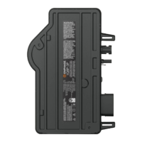
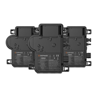
IQ8AC/IQ8HC Installation and Operation Manual
30 © 2023 Enphase Energy Inc. All rights reserved. June 2023
USM-00005-2.0
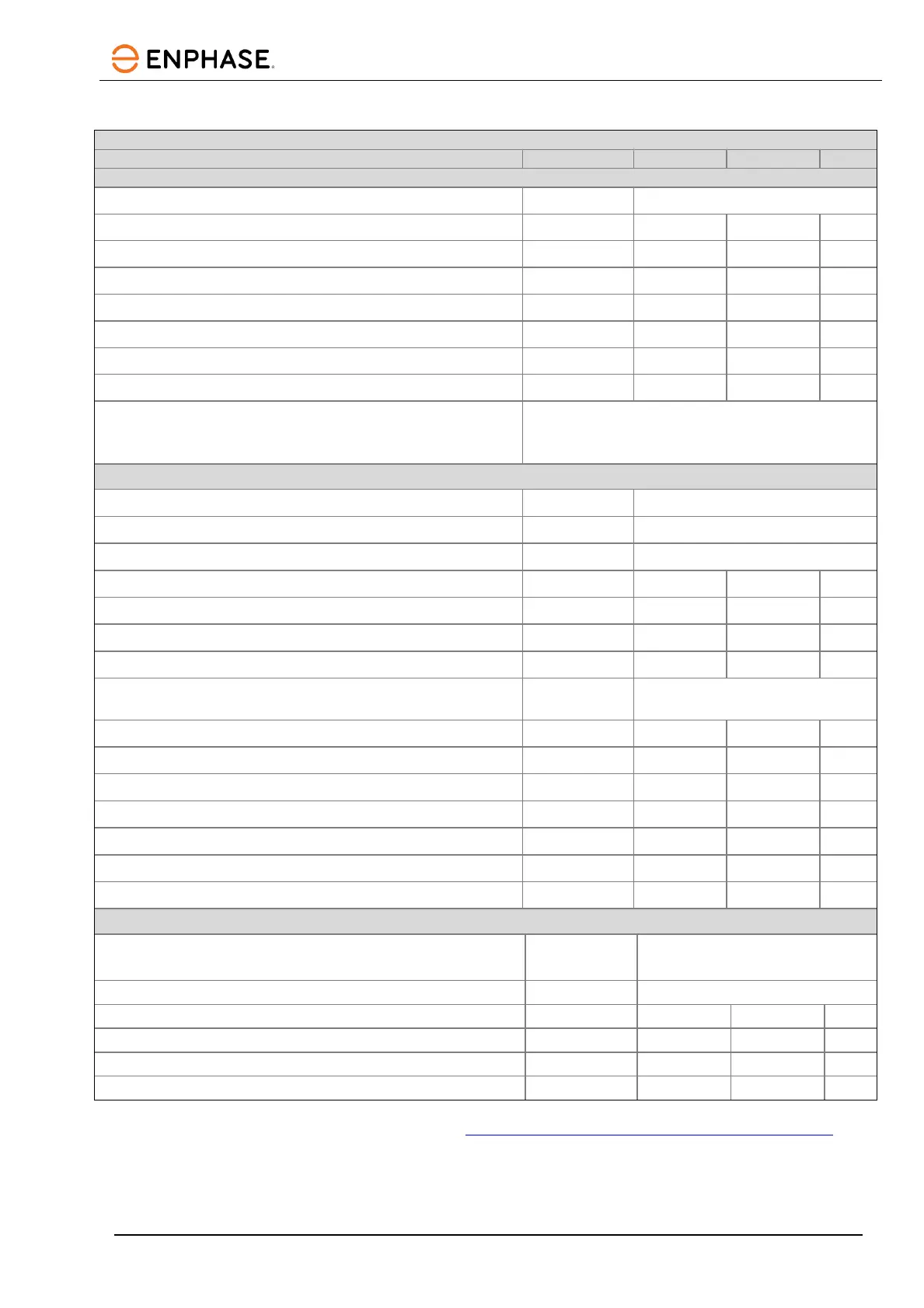
IQ8HC-72-M-INT Microinverter specifications
IQ8HC-72-M-INT Microinverter parameters
Maximum input power
1,2
W 505
Minimum/Maximum MPP voltage V 29.5 45
Minimum/Maximum operating voltage
18 49
Minimum/Maximum input voltage
18 60
Start-up input voltage
22
Maximum input current (I
dcmax
) A 14
Maximum short-circuit DC input current (I
scmax
) A 25
3
Protective class (all ports) II
PV array configuration
1x1 ungrounded array; no additional DC side
protection required; AC side protection requires max
20 A (single-phase or multi-phase)
Rated power W 380
Maximum apparent power VA 384
Power factor range 0.8 leading … 0.8 lagging
Minimum/Nominal/Maximum grid voltage
4
Vrms 184 230 276
Maximum output current
Arms 1.67
Nominal frequency Hz 50
Minimum/Maximum frequency Hz 45 55
Maximum AC output over current protection device A
20 A single-phase and 25 A multi-
phase
High AC voltage trip limit accuracy % ±1.0
Low AC voltage trip limit accuracy % ±1.0
Frequency trip limit accuracy Hz ±0.1
Trip time accuracy (for trip times or delays < 5 sec.) ±ms 33
Trip time accuracy (for trip times or delays >= 5 sec.) % 1
Overvoltage class AC port III
Power factor setting 1.0
Maximum
5
microinverters per 20 A (max) AC branch circuit
230 VAC (single-phase)/400 VAC (multi-phase)
10 (L+N)/36 (3L+N)
European weighted efficiency
% 96.8
Total harmonic distortion
Ambient air temperature range
Storage temperature range
1. No enforced DC/AC ratio. See the compatibility calculator at https://enphase.com/en-au/installers/microinverters/calculator
2. Installer should not exceed small-scale technology certificate (STC) limit on PV module wattage for claiming the STC.
3. Maximum short circuit current for modules (Isc) allowed to be paired with IQ8 Series Microinverters: 20 A (calculated with 1.25 safety
factor as per IEC 62548).
4. Nominal voltage range can be extended beyond nominal if required by the electricity network operator.
 Loading...