Checking the LEDs
3-2 Troubleshooting
Checking the LEDs
The following sections define the behavior of the LEDs on the A4 chassis models. The LEDs on all
chassis are located in the same location on the front panel.
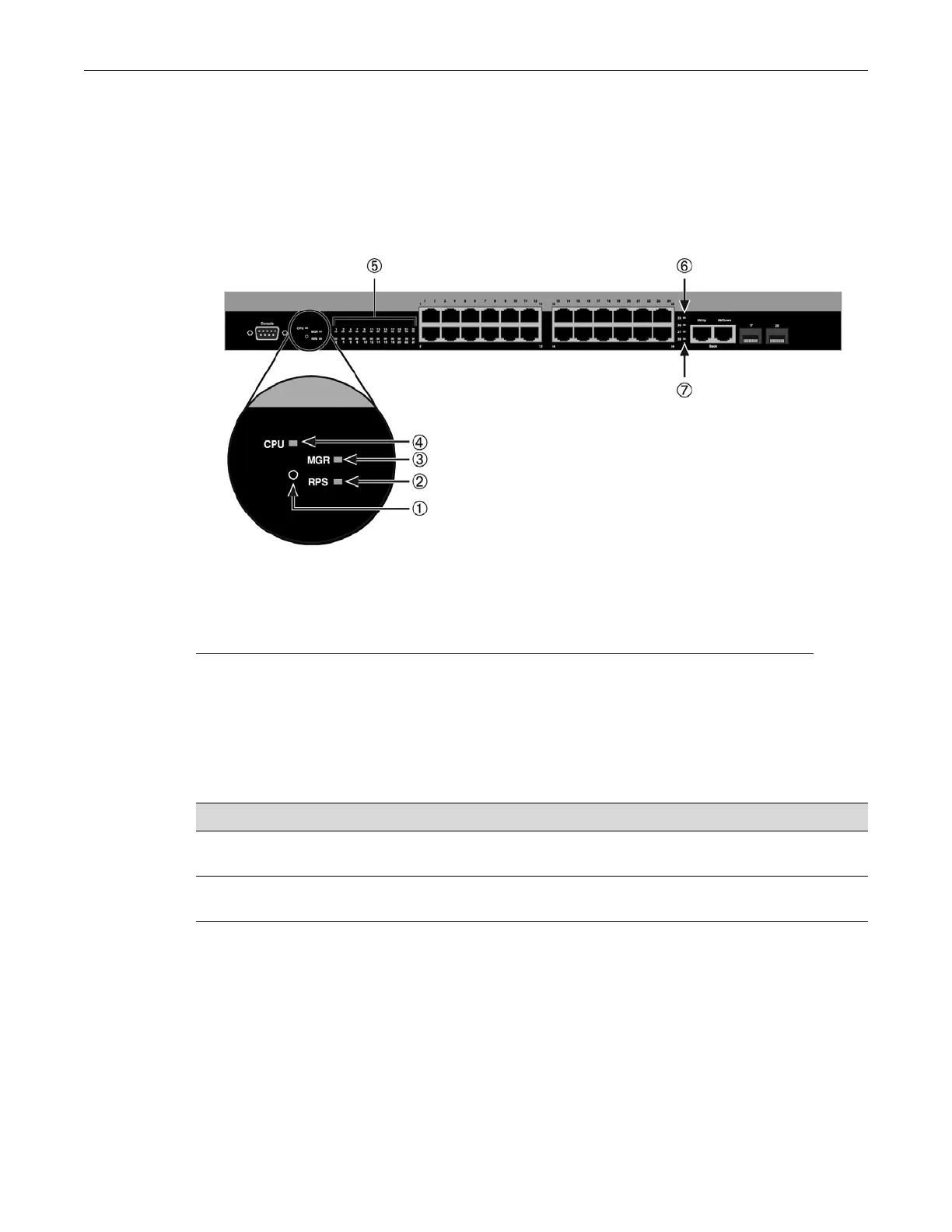
Refer to Figure 3-1 for the location of the LEDs on the chassis.
Figure 3-1 A4 Chassis LEDs (A4H124-24 shown)
MGR LED
The MGR LED indicates whether the switch is operating as a member or as the manager of the
stack, as described in Table 3-1.
1 Recessed Password Reset Button 5 10/100 MB Ports Link/Activity
2 Redundant Power Supply Active (RPS) 6 1000 MBS Stacking Port Link/Activity
3 Unit selected as Stack Manager (MGR) 7 SFP port Link/Activity
4 CPU and Power Indicator (CPU)
Table 3-1 MGR LED Definitions
Color State Recommended Action
Off Switch is operating as a member in the
stack.
None.
Green Solid. Switch is operating as the manager
of the stack.
None.
 Loading...