Rack Mounting the Switch
3-10 Hardware Installation
Guidelines for Rackmount Installation
Theinstallationsitemustbewithinreachofthenetworkcablingandmeetthe
requirementslistedbelow:
• Appropriategroundedpowerreceptaclesmustbelocatedwithin152cm(5ft)ofthe
location.
•Atemperatureofbetween0°C(32°F)and40°C(104°F)mustbemaintainedatthe
installationsitewithfluctuationsoflessthan10°C(18°F)perhour.
•Ifanoptionalredundantpowersystem
isgoingtobeinstalledandconnectedtothe
14‐pinRedundantPowerSupplyinputconnectorontherearoftheswitch,
refertothe
installationguideshippedwiththeredundantpowersystem.
Attaching Brackets and Installing in Rack
Proceedasfollowstoinstalltheswitchintoa19‐inchrack:
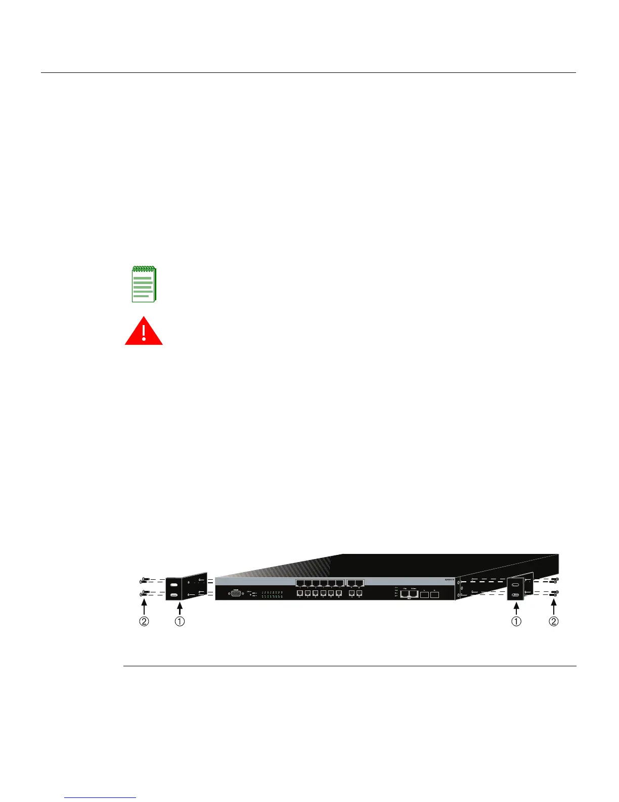
1. Attachtherackmountbracketstotheswitch,asshowninFigu re3‐6,usingtheeight
M3x6mmflatheadscrewsshippedwiththeswitch.
Figure 3-6 Attaching the Rackmount Brackets
Note: To ensure proper ventilation and prevent overheating, leave a minimum clearance
space of 5.1 cm (2.0 in.) at the left, right, and rear of the switch.
Warning: Before rack-mounting the switch, ensure that the rack can support it without
compromising stability. Otherwise, personal injury and/or equipment damage may result.
Advertencia: Antes de montar el equipo en el rack, asegurarse que el rack puede
soportar su peso sin comprometer su propia estabilidad, de otra forma, daño personal o
del equipo puede ocurrir.
Warnhinweis: Überzeugen Sie sich vor dem Einbau des Gerätes in das Rack von dessen
Stabilität, ansonsten könnten Personenschäden oder Schäden am Gerät die Folge sein.
1 Rackmount brackets 2 M3x6 mm flathead screws
 Loading...


