Safety and operating instructions
16 © Construction Tools GmbH | 33905146 01 | 2019-09-05
Original Instructions
3 Overview
3.1 Equipment description
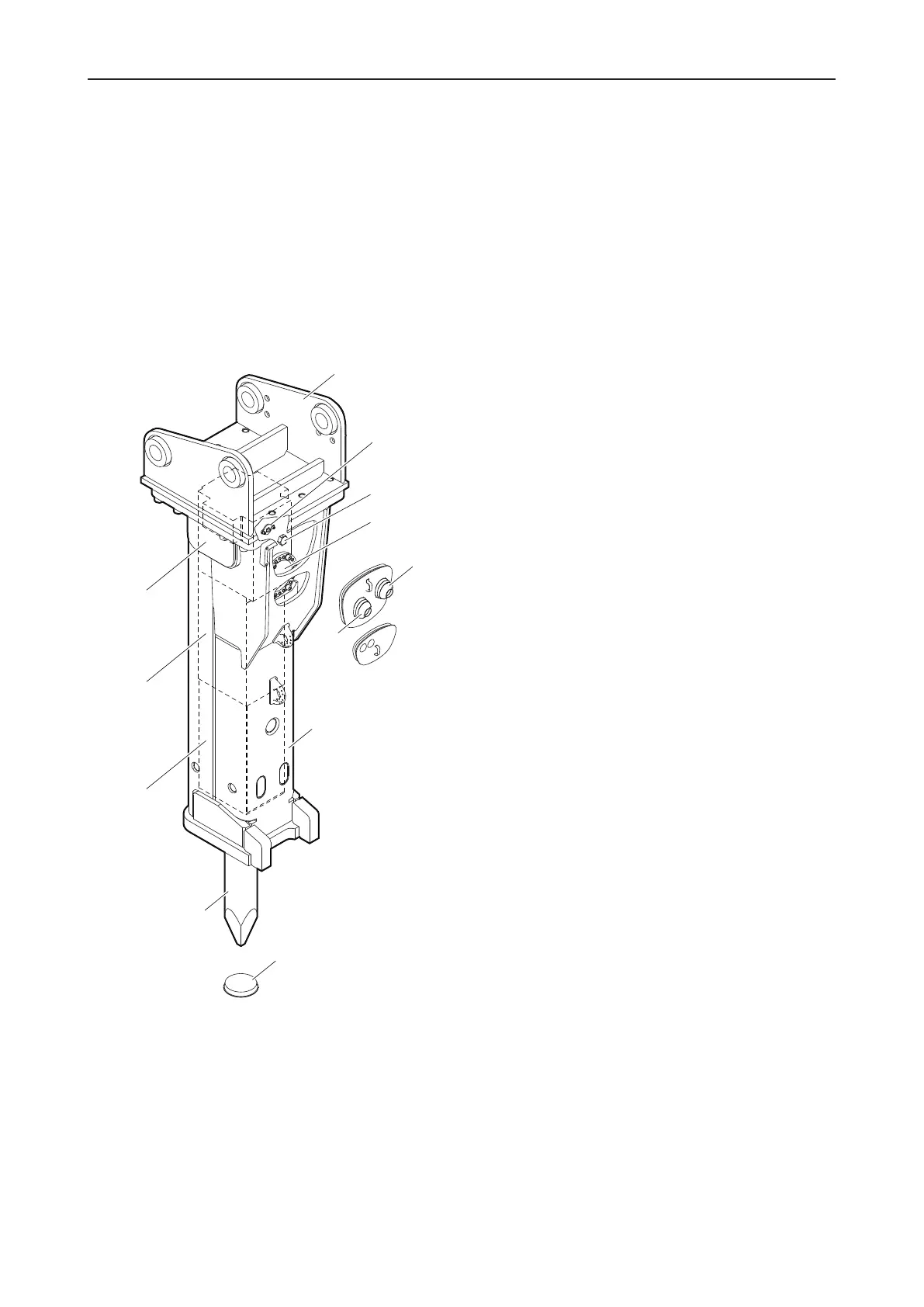
The illustration gives an overview of the main parts and
components of the hydraulic attachment. Actual details
may differ.
3.1.1 EC 140T
A. The hydraulic breaker is connected to the carrier by
the adapter plate. The adapter plate is not included
in the scope of supply of the hydraulic breaker.
B. The Stroke control valve enables you adjust the
mode of operation of the hydraulic breaker to the
particular task.
C. Non-return valve of percussion chamber ventilation
D. The HP-accumulator compensates pressure varia-
tions in the hydraulic system.
E. Tank line »T«
F. Pressure line »P«
G. The breaker box protects the percussion unit.
H. Working tool aperture protective cap
I. The working tool can be replaced as required. The
working tool is not included in the scope of supply of
the hydraulic breaker.
J. The working tool is retained in the lower breaker
part.
K. The percussion piston is guided in the cylinder.
L. The cylinder cover houses the nitrogen gas (N
2
)
filled piston accumulator and the control mechanism.
 Loading...