Safety and operating instructions
18 © Construction Tools GmbH | 33905146 01 | 2019-09-05
Original Instructions
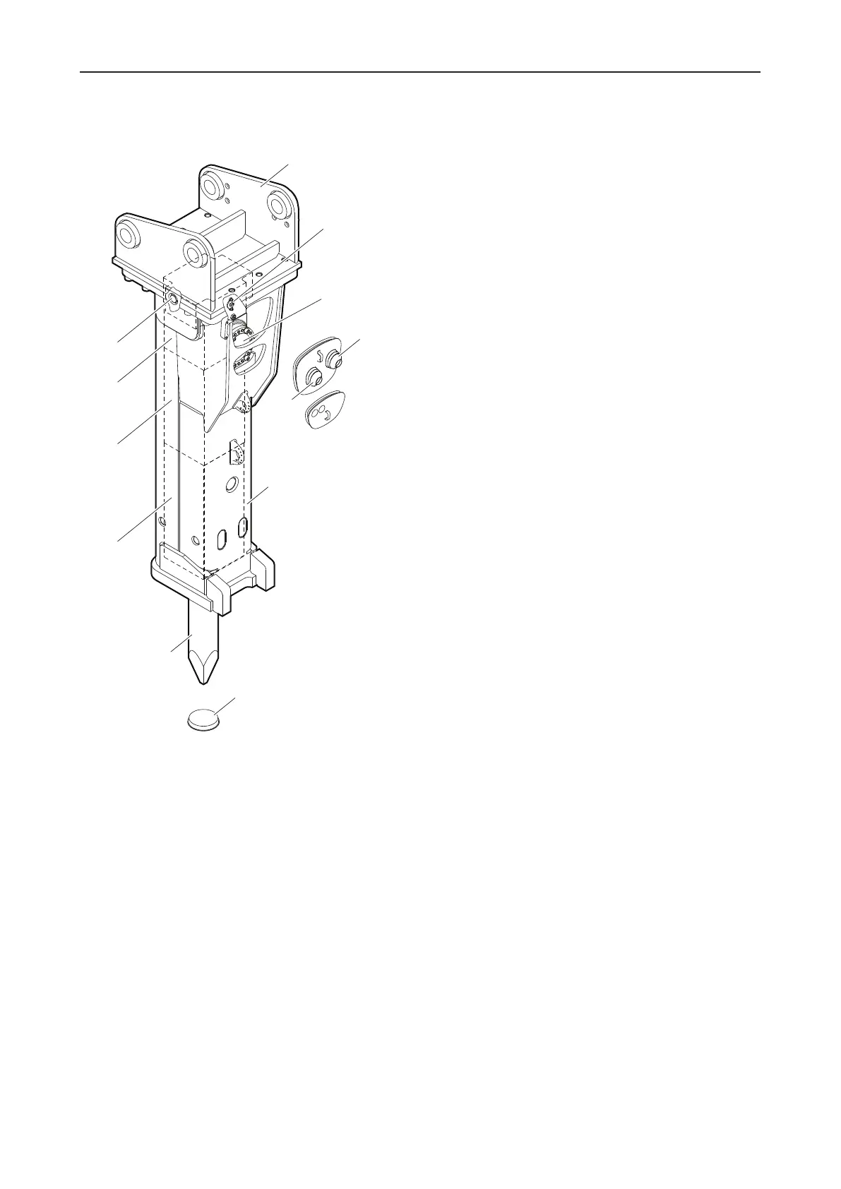
3.1.3 EC 155T, EC 165T, EC 180T
A. The hydraulic breaker is connected to the carrier by
the adapter plate. The adapter plate is not included
in the scope of supply of the hydraulic breaker.
B. The Stroke control valve enables you adjust the
mode of operation of the hydraulic breaker to the
particular task.
C. Non-return valve of percussion chamber ventilation
D. The HP-accumulator compensates pressure varia-
tions in the hydraulic system.
E. Tank line »T«
F. Pressure line »P«
G. The breaker box protects the percussion unit.
H. Working tool aperture protective cap
I. The working tool can be replaced as required. The
working tool is not included in the scope of supply of
the hydraulic breaker.
J. The working tool is retained in the lower breaker
part.
K. The percussion piston is guided in the cylinder.
L. The cylinder cover houses the nitrogen gas (N
2
)
filled piston accumulator and the control mechanism.
3.2 Function
The operation of a hydraulic breaker is described in a
greatly simplified version below:
The pressure line »P« supplies oil at the operating pres-
sure of the carrier to the hydraulic breaker. The tank line
»T« returns the oil to the tank of the carrier. The HP-ac-
cumulator compensates pressure variations in the hy-
draulic system.
The percussion piston moves up and down in the cylin-
der. When the percussion piston is in its lower position, it
impacts the working tool. The percussion energy is
transferred to the material to be broken via the working
tool.
 Loading...