Confidential
Troubleshooting Power-On Sequence 12
Epson Stylus SX230 series / SX235W series / SX430W series / SX440W series Revision B
1.2 Power-On Sequence
This section describes the power-on sequences in two conditions. The preconditions are as follows.
Condition 1: Normal power-on sequence (See Table 1-1.)
Turning on the printer after turning it off without an error.
Initial ink charge has finished and every cartridge has sufficient ink.
No paper on the paper path.
The Printhead is capped with the Cap Assy.
The CR Unit is normally fixed by the Change Lever.
Maintenance error recovery has never been performed.
Note 1: The rotation directions of the PF Motor are as follows.
Clockwise: Paper is fed normally
Counterclockwise: Paper is fed backward
*2: The conditions of the CR lock are as follows.
Red CR lock is set
White CR lock is released
*3: The fatal error occurs if there is a problem such as the fuse blew.
*4: Executed when the detected temperature is under 5
o
C (41
o
F) by the thermistor on the Printhead.
*5: The empty suction operation may occur depending on the situation.
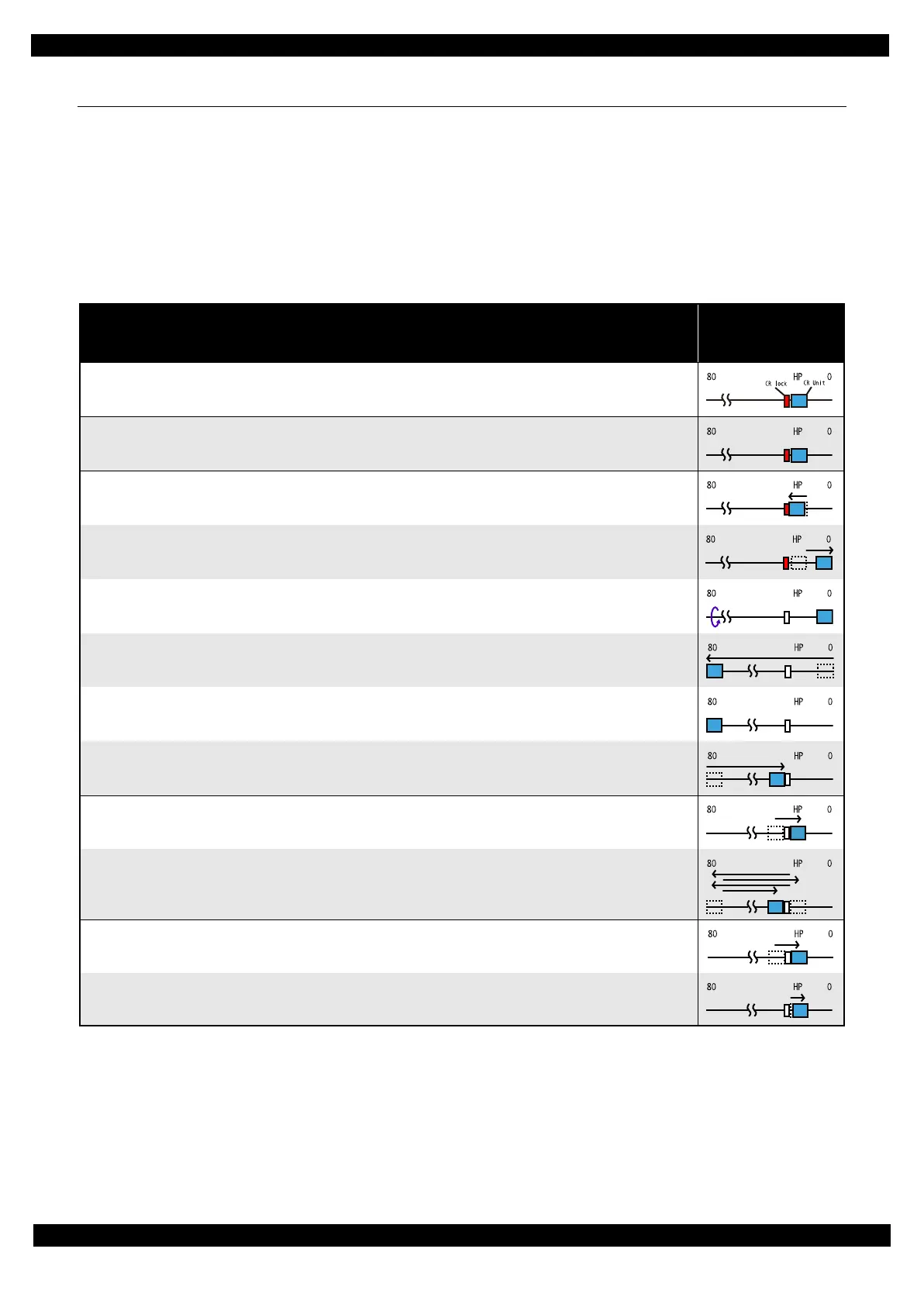
Table 1-1. Condition 1: Normal Power-on Sequence
Operation
*1
CR Unit/PF Roller
movement and
position
*2
1. Printhead initialization and fuse inspection
1-1.Initializes the Printhead, and checks for the fuse on the circuit boards in the printer.
*3
2. Checking for waste ink overflow
2-1.Checks the waste ink counter if the waste ink overflow is occurring.
3. Seeking the home position
3-1.The CR Unit moves to the 80-digit side slowly and confirms it touches the Change Lever (CR lock).
3-2.The CR Unit moves to the 0-digit side slowly and confirms it touches the Right Frame.
3-3.After the PE Sensor checks if paper exists, the PF Motor rotates clockwise for one second and releases the CR lock.
3-4.While checking if the CR Unit does not touch the Change Lever (CR lock) or the foreign material, the CR Unit
moves to the 80-digit side slowly until it touches the Left Frame.
3-5.The distance from the position where the CR Unit touched to the Left Frame is regarded as the standard distance
from the origin position, and the home position is fixed.
From then on, the CR Unit position is monitored according to the signals from the CR Encoder.
3-6.The CR Unit quickly moves to the ink end sensor detection position on the 0-digit side.
4. Low temperature operation sequence
*4
4-1.The CR Unit moves to the 0-digit side slowly.
4-2.The CR Unit quickly moves back and forth between near the Change Lever and near the Left Frame for two times.
5. Detecting ink cartridge and initializing ink system
*5
5-1.After checking the Ink End Sensor, the CR Unit moves to the ink detection position in the 0-digit side and detects
the ink remaining.
5-2.The CR Unit returns to its home position.
 Loading...