14
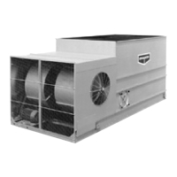
Figure 9 – LR Motor Adjustment
F
orced Dra –
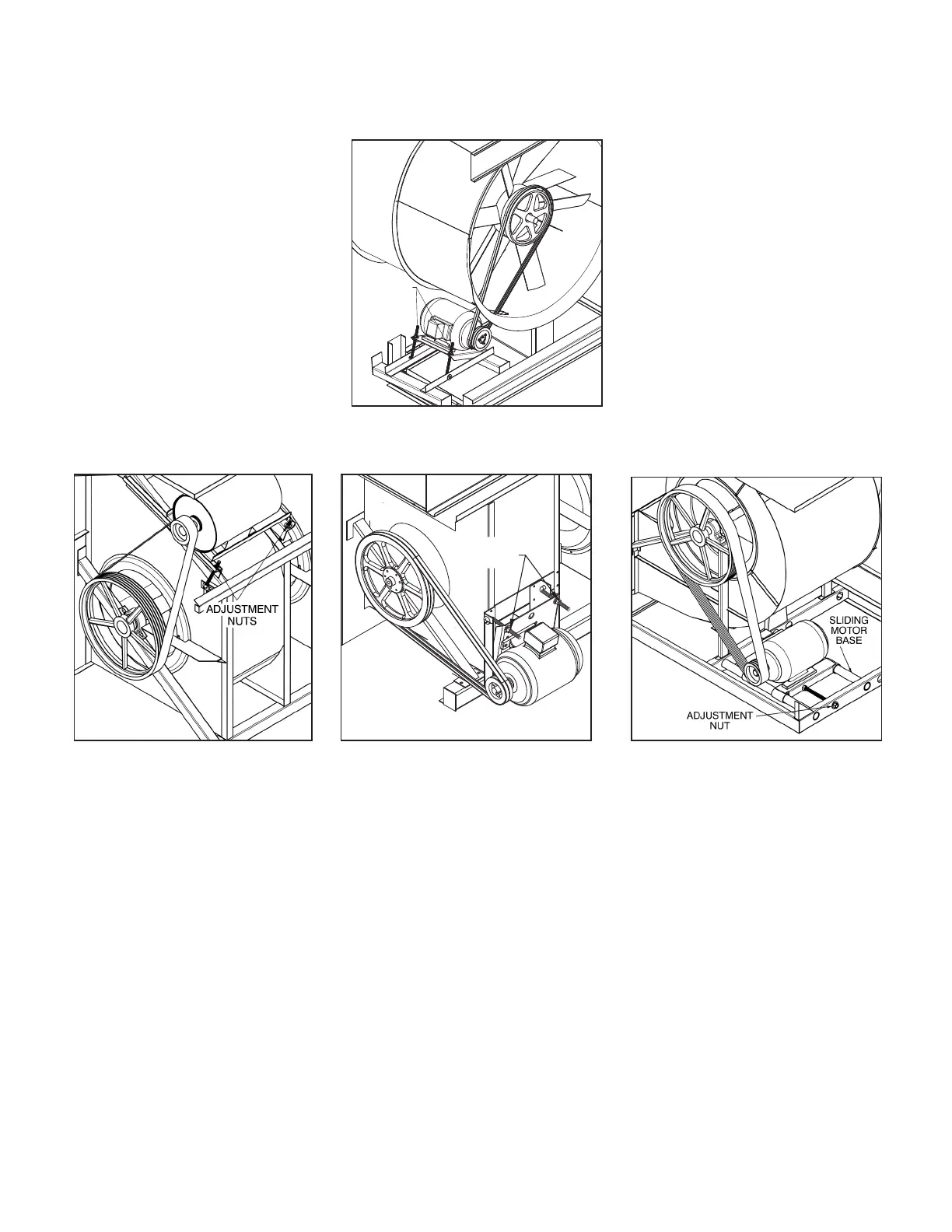
LS and PM Style forced dra units, both J-type adjustment bolts on the adjustable motor base should have an equal
amount of exposed thread for proper sheave and belt alignment.
Figure 7 – PM Style Motor Adjustment
Figure 8a – Externally Mounted
Motor, Large LS, 8X & 3M Units
Figure 8b – Externally Mounted
Motor, Small LS, 4X & 5X Units
Gear Drives
Induced dra units with gear drive systems require special maintenance. Please refer to the gear manufacturers recommended
maintenance instructions. These will be enclosed and shipped with the unit.
Air Inlet
Inspect the air inlet louvers (induced dra units) or fan screens (forced dra units) monthly to remove any paper, leaves or other debris that
may be blocking airflow into the unit.
Coil Inlet
Inspect the top coil, air inlet and spray section on all PHC units monthly.
 Loading...