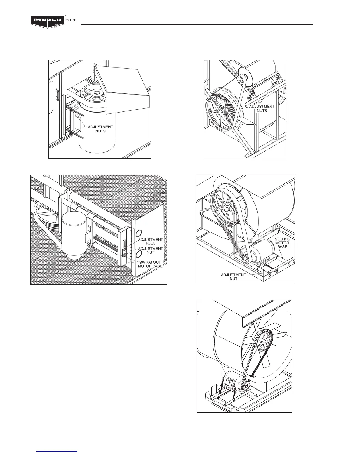
On induced draft belt driven units provided with externally mounted motors (2,3 m; 2,4 m and 4,8 m wide units), Figure 3, and
LS Style forced draft units, Figure 4, both J-type adjustment bolts on the adjustable motor base should have an equal amount of
exposed thread for proper sheave and belt alignment.
Air Inlet
Inspect the air inlet louvers (induced draft units) or fan screens
(forced draft units) monthly to remove any paper, leaves or other
debris that may be blocking airflow into the unit.
Figure 3 – Externally Mounted Motors
Figure 4 – LS units - Externally Mounted Motor
Figure 5 – Internally Mounted Motors
On induced draft units with internally mounted motors (3 m; 6 m;
3,6 m and 7,2 m wide units), and LR units, a motor adjustment
tool is provided, See figures 5 and 6. The tool will be found on the
adjustment nut. To use, place the hex end over the adjustment nut.
Tension the belt by turning the nut counterclockwise. When the belts
are properly tensioned, tighten the lock nut.
ADJUSTMENT
NUT
Figure 7 – PM Style Motor Adjustment
Figure 6 – LR Motor Adjustment
 Loading...