Operating Level of Water in Cold Water Basin
The operating level should be checked monthly to make sure the water level is correct. Refer to Table 3 for unit specific levels.
At initial start up or after the unit has been drained, the unit must be filled to the overflow level. Overflow is above the normal
operating level and accommodates the volume of water normally in suspension in the water distribution system and the riser piping.
The water level should always be above the strainer. Check by running the pump with the fan motors off and observing the water
level through the access door or remove the air inlet louver.
Water Make Up Valve
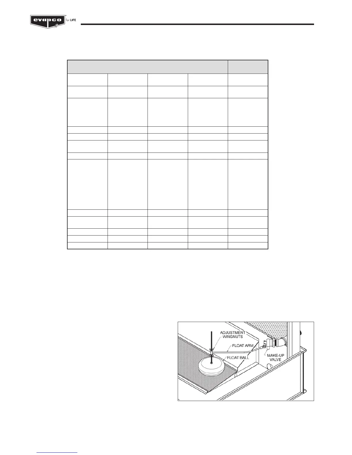
A mechanical float valve assembly is provided as standard
equipment on the evaporative cooling unit (unless the unit has
been ordered with an optional electronic water level control
package or the unit is arranged for remote sump operation). The
make up valve is easily accessible from outside the unit through
the access door or removable air inlet louver. The make up valve
is a bronze valve connected to a float arm assembly and is
activated by a large foam filled plastic float. The float is mounted
on an all-thread rod held in place by wing nuts. The water level
in the basin is adjusted by repositioning the float and all-thread
using the wing nuts. Refer to Figure 12 for details.
The make up valve assembly should be inspected monthly and
adjusted as required. The valve should be inspected annually
for leakage and if necessary, the valve seat should be replaced.
The make up water pressure for the mechanical valve should be
maintained between 140 and 340 kPa.
* Measured from lowest point on basin floor.
Table 3 - Recommended Operating Water Level
Figure 12 – Mechanical Water Make Up Valve
Model Number Operating
Level
ATW
ATW
9
64
through
through
48
866
230 mm
280 mm
ESWA
ESWA
72
144
through
through
142
216
280 mm
280 mm
LSWA
LSWA
LSWA
LSWA
LSWA
20
91
116
135
174
through
and
and
and
and
87
182
232
270
348
280 mm
300 mm
300 mm
380 mm
380 mm
LRW 18 through 379 200 mm
C-ATW 67-3H through 133-6J 280 mm
eco-ATW
eco-ATW
0,9 m wide
2,3 m wide
and
through
1,2 m wide
7,3 m wide
230 mm
280 mm
eco-ATWE 2,3 m wide through 7,3 m wide 280 mm
LSCE
LSCE
LSCE
LSCE
LSCE
LSCE
LSCE
LSCE
LSCE
36
281
591
400
800
410
820
550
1100
through
through
through
through
through
through
through
through
through
385
386
770
515
1030
560
1120
805
1610
280 mm
300 mm
300 mm
300 mm
300 mm
380 mm
380 mm
380 mm
380 mm
LRC 25 through 379 200 mm
ATC
ATC
50E
M170E
through
through
165E
3714E
230 mm
280 mm
C-ATC 181 through 504 280 mm
PMCQ 316 through 1786 360 mm
eco-ATC 176 through 4086 280 mm
 Loading...