13
Identify and Lock-out Harmful Resonant Frequencies
AVariableFrequencyDrive(VFD)fansystem,unliketraditionalxed-speedsystems,isdesignedtooperatebetween25%
(13Hz) and 100% (50Hz) speeds, which creates an opportunity for operation where resonant frequencies exist. Sustained
operation at resonant frequencies may lead to excessive vibration, fatigue of structural components and/or drive system noise
and failure. Owners and operators must anticipate the existence of resonant frequencies and lock out frequencies during
start-up and commissioning in order to prevent drive system operational problems and structural damage. As a part of the
normalstart-upandcommissionprocesses,resonantfrequenciesshouldbeidentiedandlocked-outintheVFD’ssoftware.
The unit’s supporting structure, external piping, and accessories contribute to the overall harmonic make-up and stiffness
ofthesystem.ThechoiceofVFDwillalsohaveasignicantinuenceonhowthesystembehaves.Consequently,not
allresonantfrequenciescanbedeterminedinadvanceatthemanufacturer’sfactoryduringnalinspectionandtesting.
Relevantresonantfrequencies(iftheyoccur)canonlybeidentiedaccuratelyaftertheinstallationinthesystem.
Tocheckforresonantfrequenciesintheeld,arun-upandrun-downtestmustbeperformed.Additionally,VFDcarrier
frequencies should be adjusted to best align the VFD with the electrical system. Refer to your drive’s start-up procedures
for additional information and instruction.
The procedure of checking for resonant frequencies requires stepping through the VFD’s operating range at (2) Hz
intervals from the lowest operating frequency to full speed. At each step, pause long enough for the fan to reach steady-
state. Note changes in unit vibration during this time. Repeat from full speed to minimum speed. Should vibration-inducing
frequencies exist, the run-up and run-down test will isolate the resonant frequencies which then must then be locked-out in
the VFD programming.
Recirculated Water System – Routine Maintenance
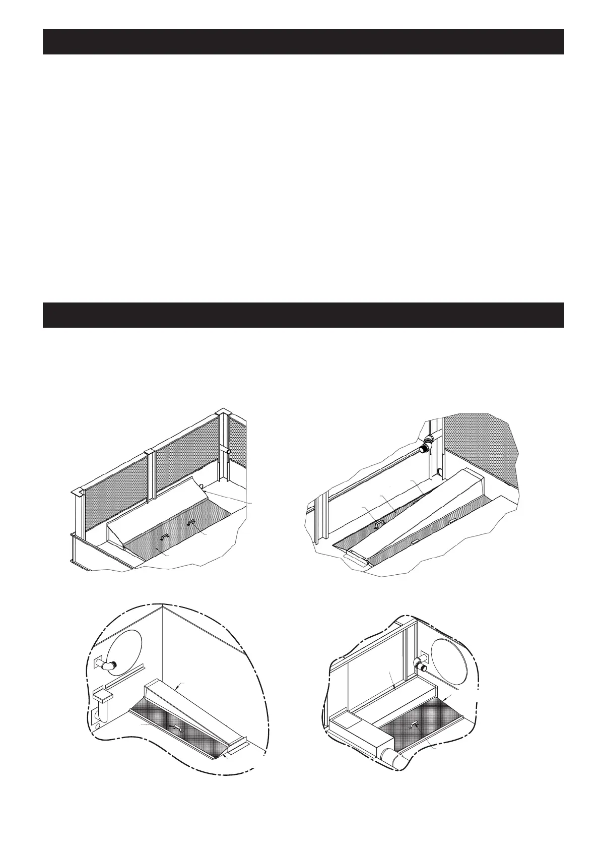
Suction Strainer in Cold Water Basin
Thepanstrainershouldberemovedandcleanedmonthlyorasoftenasnecessary.Thesuctionstraineristherst
line of defense in keeping debris out of the system. Make certain that the strainer is properly located over the pump
suction, alongside the anti-vortexing hood.
STRAINER
ASSEMBLY
STRAINER
HANDLE
ANTI-VORTEXING
HOOD
ANTI-VORTEXING
HOOD
STRAINER
ASSEMBLY
STRAINER
HANDLE
Figure 8 – Single Strainer Assembly Figure 9 – Dual Strainer Assembly
Figure 10 – LSTE / PMTQ Strainer Assembly Figure 11 – LPT Strainer Assembly
STRAINER
ASSEMBLY
STRAINER
HANDLE
ANTI-VORTEXING
HOOD
ANTI-VORTEXING
HOOD
STRAINER
ASSEMBLY
STRAINER
HANDLE
 Loading...