video material.
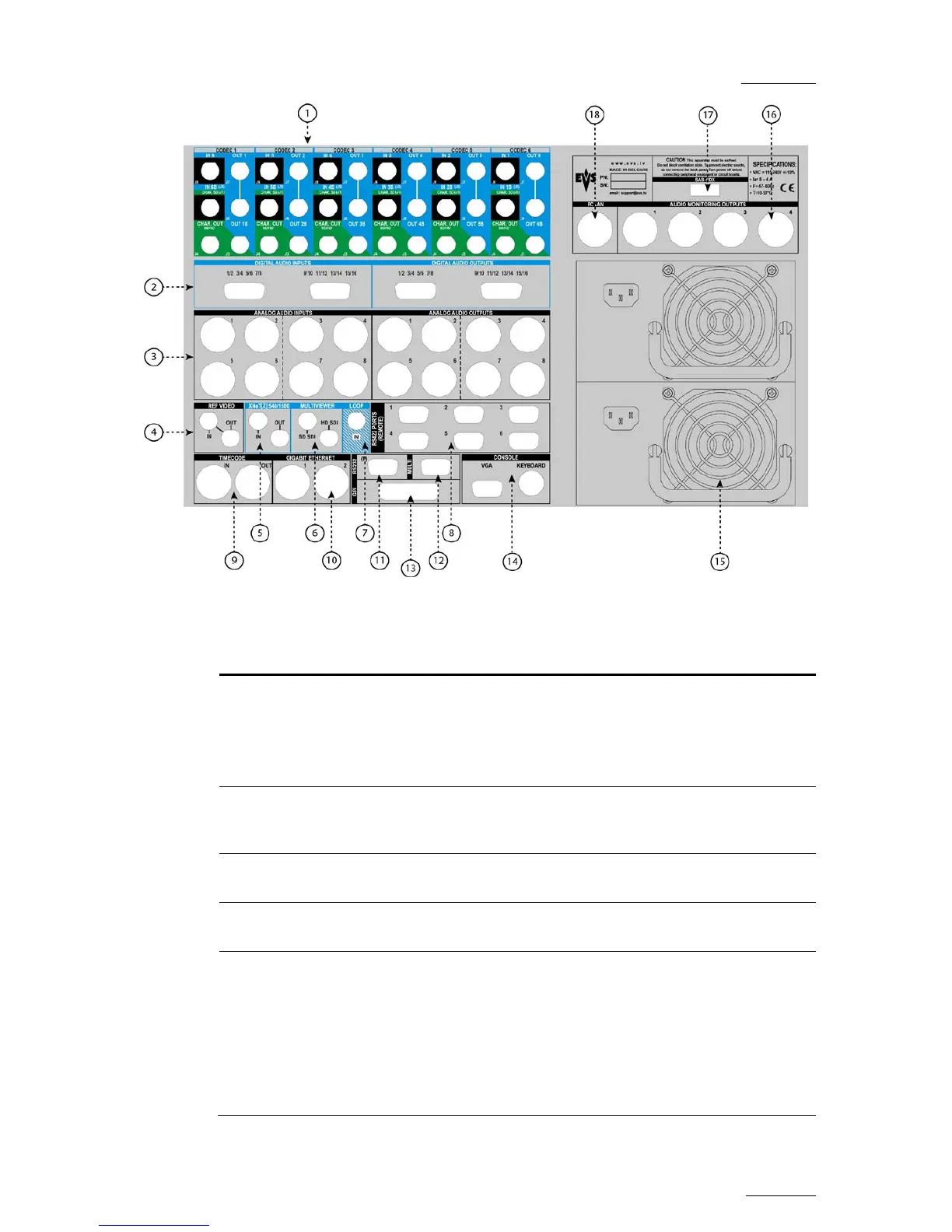
Each connector on a codec module is connected to
the corresponding J connector on the V3X COD A or
COD B module of a V3X board.
2. Digital Audio
Inputs / Outputs
Multi-pin connectors (DB15) (as presented), BNC or
XLR connectors for audio inputs and outputs in
digital format.
3. Analog Audio
Inputs / Outputs
AES XLR connectors for audio input and outputs in
analog format.
4. Ref Video Allows the EVS server to receive or send back the
analog genlock reference signal.
5. XNet2 Allows the interconnection of EVS servers, XF2
and/or XStore in an XNet2 network.
The IN connector of a server is connected to the OUT
connector of another server, and so on to form a
closed network.
 Loading...


![Preview: EVS XT[2]](https://data.easymanua.ls/products/617905/200x200/evs-xt-2.webp)


