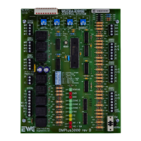
BMPlus3000
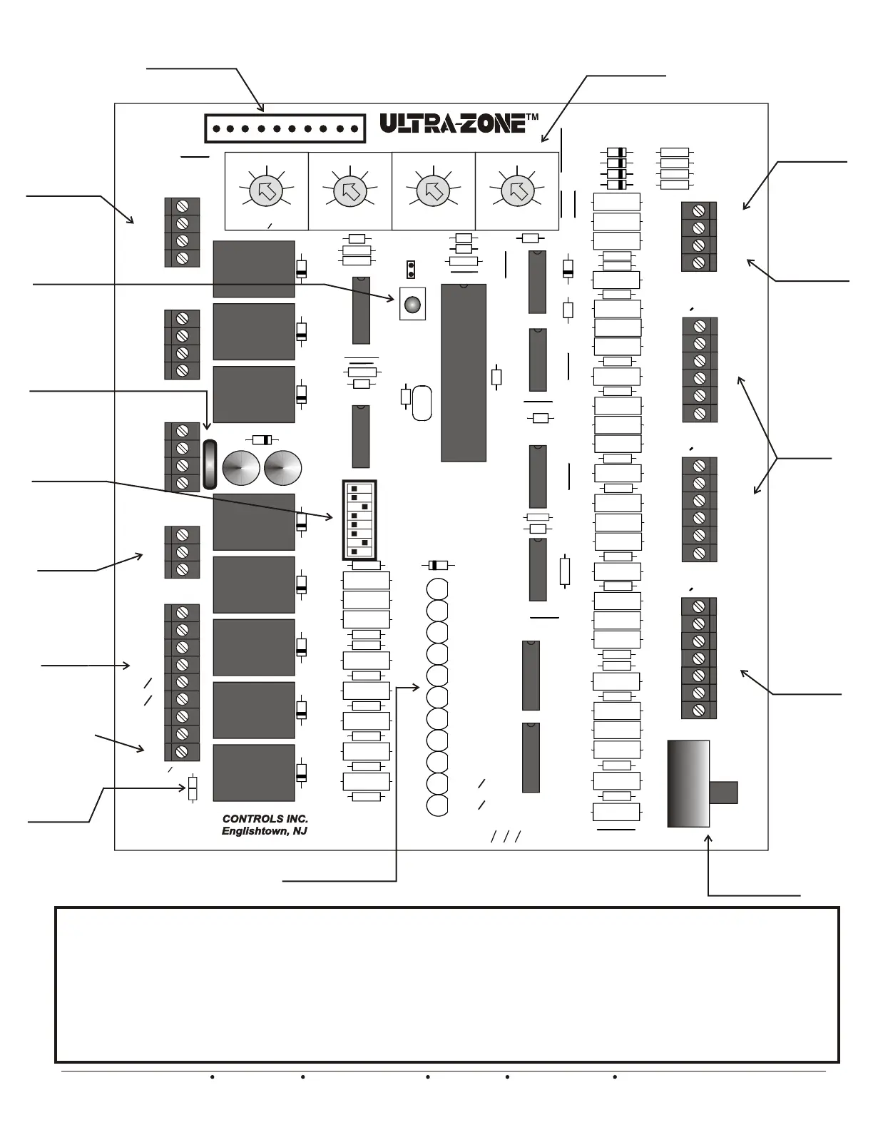
3 Zone Main
Module
Rugged 10 pin
Expansion Header
Supply Air
Sensor
Connections
Outdoor Air
Sensor
Connections
Rugged Damper
Motor Terminal
Blocks
User Friendly
Adjustable
Potentiometers
On-Board
Emergency Switch
On-Board
CUTTABLE
Rc/Rh Link
Isolated HVAC
System
Terminal
Block
Rugged
Thermostat
Terminal
Blocks
Multi
Functional
Zone 1
Thermostat
Terminal
Block
Easy Setup
8 switch Bank
Dual Function
Reset
Button
Polarized
Power Input
Terminals
The BMPlus 3000 Zone Control System includes Module to Module Factory Wiring. We power up the Expansion Modules
for you. The XM2 Expansion module includes a Status LED and Damper Status LED’s.
See page 11 and 12 for drawing representations of a 5 and 7 zone system and appropriate dip switch settings.
All you have to do is:
1. Set the dip switches to your specific application.
2. Connect your thermostats, dampers and system wiring.
3. Power up the Main Module
4. Check System Operation.
5. Enjoy.
Protective
header cap not
shown for clarity
EWC Controls Inc. 385 Highway 33 Englishtown, NJ 07726 800-446-3110 FAX 732-446-5362 E-Mail- info@ewccontrols.com
11
Thermal Circuit
Breaker
Isolated Common
terminal. Useful
when HVAC
troubleshooting
System Status LED’s
Figure 19
J
1
ZONE3
MOTOR
ZONE2
MOTOR
MOTOR
ZONE1
24
T’FORMER
VAC
SYSTEM
M6
M4
M2
M1
M6
M4
M2
M1
M6
M4
M2
M1
R
C
G
Y2
Y1
O
RH
RC
W1
B
W2
E
LINK
RH
RC
D
4
3
D
C
1
C
2
+
+
SAS
SAS
OAS
OAS
C
W/E
O/B
Y
R
G
ONE
ZONE
EM
NORM
SW
4
ZONE1
STAT
T
D
11
D
12
D
13
D
10
2
ND STAGE HEAT
DIFFERENTIAL
LIMIT
HIGH
TEMPLOW TEMP
LIMIT
TIMER
OAS
STAGING
47
5
40
33
26
19
12
110
120
130
140
150
160
170
52
49
46
43
40
37
34
42
35
28
21
14
7
OFF
BMPlus3000 rev B
W
2
EM
B
1
W
1
2
Y
Y
ZONE
ZONE
ZONE
FAN
1
2
3
STATUS
OAS
SAS
38
39
R
R
R
37
R
36
R
76
77
R
72
R
73
R
R
70
69
R
67
R
68
R
65
R
R
64
71
R
R
63
62
R
R
61
60
R
59
R
58
R
R
57
56
R
55
R
54
R
R
78
79
R
53
R
52
R
R
51
50
R
49
R
48
R
R
47
46
R
45
R
81
R
R
40
43
R
R
42
41
R
10
LED
9
LED
8
LED
7
LED
6
LED
5
LED
4
LED
3
LED
2
LED
1
LED
11
LED
6
U
U
7
U
8
5
U
4
U
U
2
3
U
U
1
1
K
2
K
3
K
4
K
5
K
6
K
7
K
8
K
R
1
2
R
3
R
4
R
RESET
1
D
2
D
C
11
8
C
7
C
15
C
5
C
R
35
C
10
13
C
Y
1
21
D
1
Z
14
C
SW
3
33
R
32
R
31
R
30
R
8
D
29
R
R
28
27
R
26
R
7
D
25
R
R
24
23
R
22
R
6
D
21
R
R
20
R
19
5
D
D
9
34
R
GAS
OFF
OFF
OAS
HC
HP
OTHER
HP
TIMER
ON
HYDRONIC
ON
O
B
DF
<
<
<
<
<
< >
>
>
>
>
>
>
<
>
<
SYSTEM
HP
CONV
50
TSTATS
RV
STAGING
RULE
SAS
FAN
E
W
C
SYSTEM
CONTROL
%
C
C
W/E
O/B
Y
R
G
ZONE3
STAT
T
F1
C
W/E
O/B
Y
R
G
9
C
66
R
82
R
R
44
R
14
R
R
15
16
U
9
12
C
R
13
ZONE2
STAT
T
 Loading...