DAMPER WIRING AND CONFIGURATIONDAMPER WIRING AND CONFIGURATION
Note: All zone dampers default to the "OPEN"
position after a purge delay has occurred.
Dampers also default “OPEN” during
changeover & short cycle delays, and when
all zone demands are satisfied, and no
signals are detected from the thermostats.
6
4
1
PC
PO
COM
ZONE
MOTOR
M1
M6
M4
M2
ZONE
MOTOR
M1
M6
M4
M2
6
4
1
PC
PO
COM
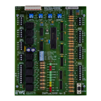
Common 24vac
Constant 24vac HOT
24vac to Open a damper(s)
24vac to Close a damper(s)
Terminal M1
Terminal M2
Terminal M4
Terminal M6
ZONE MODULE DAMPER
MOTOR TERMINAL BLOCK
DESIGNATION & FUNCTION
.
.
A Spring Open Damper is wired to M1 & M6
A Spring Close Damper is wired to M1 & M4
{
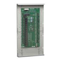
MA-ESR
NC NO C M M
Auxilary
SPDT
End Switch
Dry Contacts
Rated for
24vac only
REFERENCE THESE DIAGRAMS PRIOR TO
INSTALLATION AND POWER WIRING. DOING SO WILL
SAVE TIME AND LABOR LATER ON.
Figure 13
Figure 15
Figure 16
All Models RSD Damper Wiring
All Models ND, URD and SID Damper Wiring
Figure 14
On all these dampers and most older style
dampers, including competitor’s dampers,
always wire up number to number or designation
to designation.
Do not overload your transformer!
Contact EWC Controls Technical Support when you
are on the job site for assistance with damper wiring.
Have a Multi-Meter, pocket screw driver and wire
snips on hand.
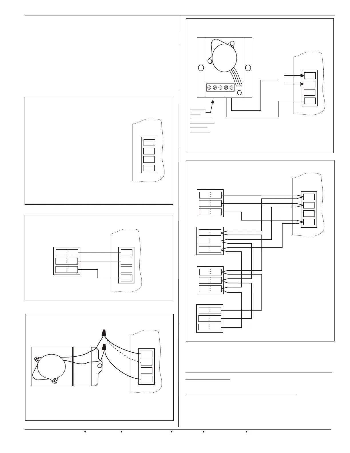
Multiple ND and/or URD
Damper Wiring on a Single Zone
(2-4 Dampers)
Figure 17
EWC Controls Inc. 385 Highway 33 Englishtown, NJ 07726 800-446-3110 FAX 732-446-5362 E-Mail- info@ewccontrols.com
8
Either one
Not both
MA-RSD
A Spring Open Damper is wired to M1 & M6
A Spring Close Damper is wired to M1 & M4
All Models ESR Damper Wiring
ZONE
MOTOR
M1
M6
M4
M2
ZONE
MOTOR
M1
M6
M4
M2
ZONE
MOTOR
M1
M6
M4
M2
6
4
1
PC
PO
COM
6
4
1
PC
PO
COM
NOTE: Do not connect more
than 4 motor actuators in a
series configuration. That will
decrease the chances of poor
electrical connections and
voltage drop issues. If wiring
more than 4 dampers see figure
18.
6
4
1
PC
PO
COM
 Loading...