SYSTEM WIRING
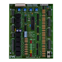
Typical gas or Electric Furnace with
A/C. Note the common “C” wire is
connected to the SYSTEM terminal
block of the BMPlus 3000.
Typical heat pump system wiring with electric resistance or
Gas backup heat (No Dual Fuel kit required). This diagram
applies to air cooled or geothermal / ground source
systems.
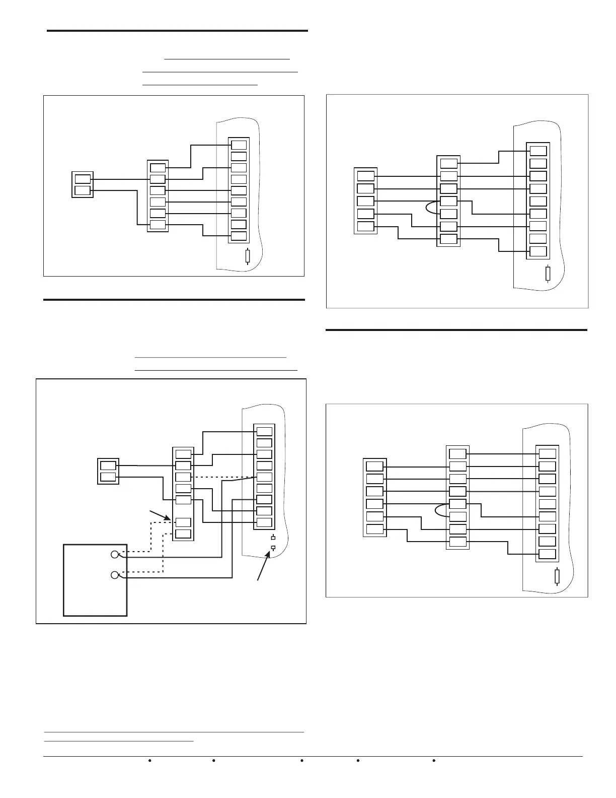
Wiring diagram for a typical oil burner,
hydronic zone / Air handler with A/C.
Cut the Rc / Rh link on the BMPlus
Panel for systems requiring isolation.
Single
Transformer
Gas or Electric
Furnace & A/C
1 or 2 Stage Heat
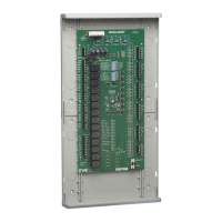
Conventional or Dual Fuel 2 Heat / 1 Cool Heatpump
with O (Cool) Type Reversing Valve
Two
Transformer
Systems
Figure 7 Single transformer Conventional system.
Figure 9 -- 2 Heat / 1 Cool Heat Pump System
Figure 8 Two transformer Oil or Hydronic / A/C system.
Conventional or
Dual Fuel 3 Heat /
2 Cool Heat Pump
with O (Cool) Type
Reversing Valve
SYSTEM
O
W1/B
G
Y2
Y1
RH
RC
C
W2/E
RC/RH
LINK
Y
R
C
T
T
Y
W
G
C
Figure 10 – 3 Heat / 2 Cool Heatpump System
HEAT PUMP
2 STAGE
BMPlus 3000
**Note that a Conventional & Dual fuel heat pump wire up more or less the
same. The difference is how auxiliary heat operates. In a Conventional
system, the indoor fan & the compressor continues to run when auxiliary
energizes. In a Dual Fuel system, the indoor fan & the compressor shuts
down when auxiliary energizes. The BMPlus 3000 will perform these
functions automatically. All you have to do is set the dip switches to the
correct settings. Select CONV or DF at dip switch #2. Install regular
Heat/Cool thermostats and choose to activate auxiliary heat by TIMER or by
OUTSIDE AIR TEMPERATURE. (Optional Sensor required). Or you may
choose to install Heat Pump Thermostats on all zones. When the thermostat
auxiliary heat demand is satisfied, the BMPlus 3000 will stage down, unless
DF or OAS has been selected and the outdoor temperature is lower than the
OAS changeover setting. In that case the system will continue in FUEL
mode, until all current heating demands are satisfied.
* Note: Your Air Handler may include a W terminal. That means
it may have it’s own isolation circuit. If you can confirm this,
simply connect the W1/B terminal to the W terminal on the air
handler. Do not cut the Rc/ Rh jumper. Wire up your Oil Burner,
Circulator relay, or Hydronic Zone valve to the isolation
contacts or wires provided in the air handler. The fan is
controlled via the time delay relay inside the air handler.
Don’t worry if you accidentally cut the Rc/Rh link. Just install your
own jumper across the Rc/Rh terminals!
AIR HANDLER
OR 1 0R 2 STAGE
GAS FURNACE
HEAT PUMP
1 STAGE
BMPlus 3000
Conventional or Dual Fuel Heat Pump wiring
with 3 Heat / 2 Cool. With electric or Gas
Furnace Backup (No dual fuel kit is required).
This diagram applies to air cooled or
geothermal / ground source systems.
EWC Controls Inc. 385 Highway 33 Englishtown, NJ 07726 800-446-3110 FAX 732-446-5362 E-Mail- info@ewccontrols.com
6
You may need
to Cut the
RC/RH Link
Boiler Control
OR
Zone Valve Control
OR
Circulator Control
OIL
BURNER
PRIMARY
CONTROL
OR
TYPICAL FAN
CENTER
TERMINAL
BLOCK
OUTDOOR
CONDENSING
UNIT
T
T
ISOLATION
TERMINALS
OR WIRES
BMPlus 3000
Y
C
SYSTEM
O
W1/B
G
Y2
Y1
RH
RC
C
W2/E
RC/RH
LINK
Y
W1
W2
R
C
G
BMPlus 3000
GAS or Electric
Furnace
1or2 STAGE
OUTDOOR
CONDENSING
UNIT
To make troubleshooting
easier, connect the “C”
Common from the Furnace
to the BMPlus. If you don’t
connect it, it’s OK.
SYSTEM
O
W1/B
G
Y2
Y1
RH
RC
C
W2/E
RC/RH
LINK
O
X/W
R
C
Y
O
W1
W2
R
C
G
Y
SYSTEM
O
W1/B
G
Y2
Y1
RH
RC
C
W2/E
RC/RH
LINK
O
X/W
R
C
O
W1
W2
R
C
G
Y1
*
Y2
Y1
Y2
AIR HANDLER
OR 1 0R 2 STAGE
GAS FURNACE
 Loading...