THERMOSTAT WIRING CONTINUED
EWC Controls Inc. 385 Highway 33 Englishtown, NJ 07726 800-446-3110 FAX 732-446-5362 E-Mail- info@ewccontrols.com
5
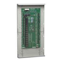
Figure 5
Wiring a split circuit thermostat to operate a
Radiant floor heating or Baseboard heating
Hydronic system. The BMPlus 3000 controls the
cooling only in this type of configuration.
WIRING FOR RADIANT FLOOR HEAT
To Radiant floor / Baseboard heat
zone valve or pump relay
W
RH
GRC
Y
ZONE2
T’STAT
Y
R
G
O/B
W/E
C
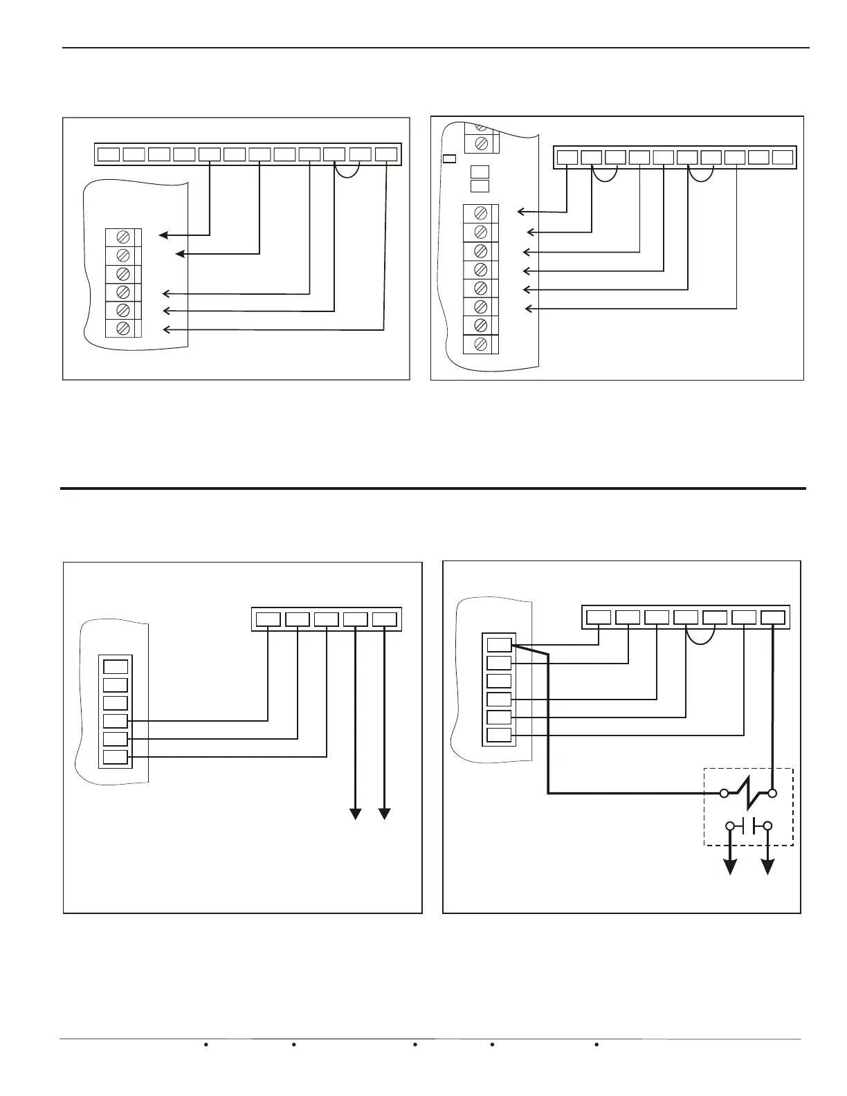
Figure 6
Wiring for a Radiant floor loop as the first
stage of heat via the isolation relay and 2nd
stage Forced Air heat is controlled through the
zone panel.
ZONE2
T’STAT
Y
R
G
O/B
W/E
C
G
W1
RH
RCY
W2
C
To Radiant floor / Baseboard heat
zone valve or pump relay
SPST 24vac
Isolation Relay
HEAT/COOL
THERMOSTAT
MULTISTAGE HEAT/COOL
THERMOSTAT
*
Thermostat should be battery powered.
*
Figure 3.
ZONE
T'STAT
C
W/E
Y
R
G
O/B
C
W/E
B
W2
Y1
O
RC
RH
MODEL EWT-955WH
H
D
Y2
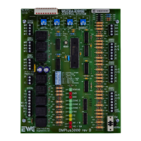
Model EWT-955WH Wireless Thermostat:
Configured for 1 heat 1 cool.
See thermostat instructions for further
TYPICAL 24v WIRELESS THERMOSTAT
Typical “Wi-Fi” Thermostat Configured for
2 heat & 1 cool Heat Pump. See
thermostat instructions for further details.
Figure 4
W/E
C
G
W2
O
Y1
RC
EWT-855i “Wi-Fi” Thermostat
C
W/E
Y
R
G
ONE
ZONE
O/B
1
ZONE
DRY R
R
LED
RH
Y2 B
TYPICAL 24v WiFi THERMOSTAT
*
*
Field installed jumper.
G
 Loading...