Drives
3.
180
Ref.1912
DDS
HARDWARE
· 132 ·
X6 connector
This connector of the modular drive identified as X6 may be:
A SERCOS-II interface connector.
A CAN interface connector.
An RS-232/422 serial line connector ·only on MMC drives·.
X6. SERCOS-II
This connector consists of a SERCOS-II signal receiver and emitter (IN,
OUT) and may be used to connect the modules of the DDS system with the
CNC that governs them. The connection is made through fiber optic lines
and it has a ring structure.
It will always come with a node selecting rotary switch ·NODE· that lets
identify each drive within the system.
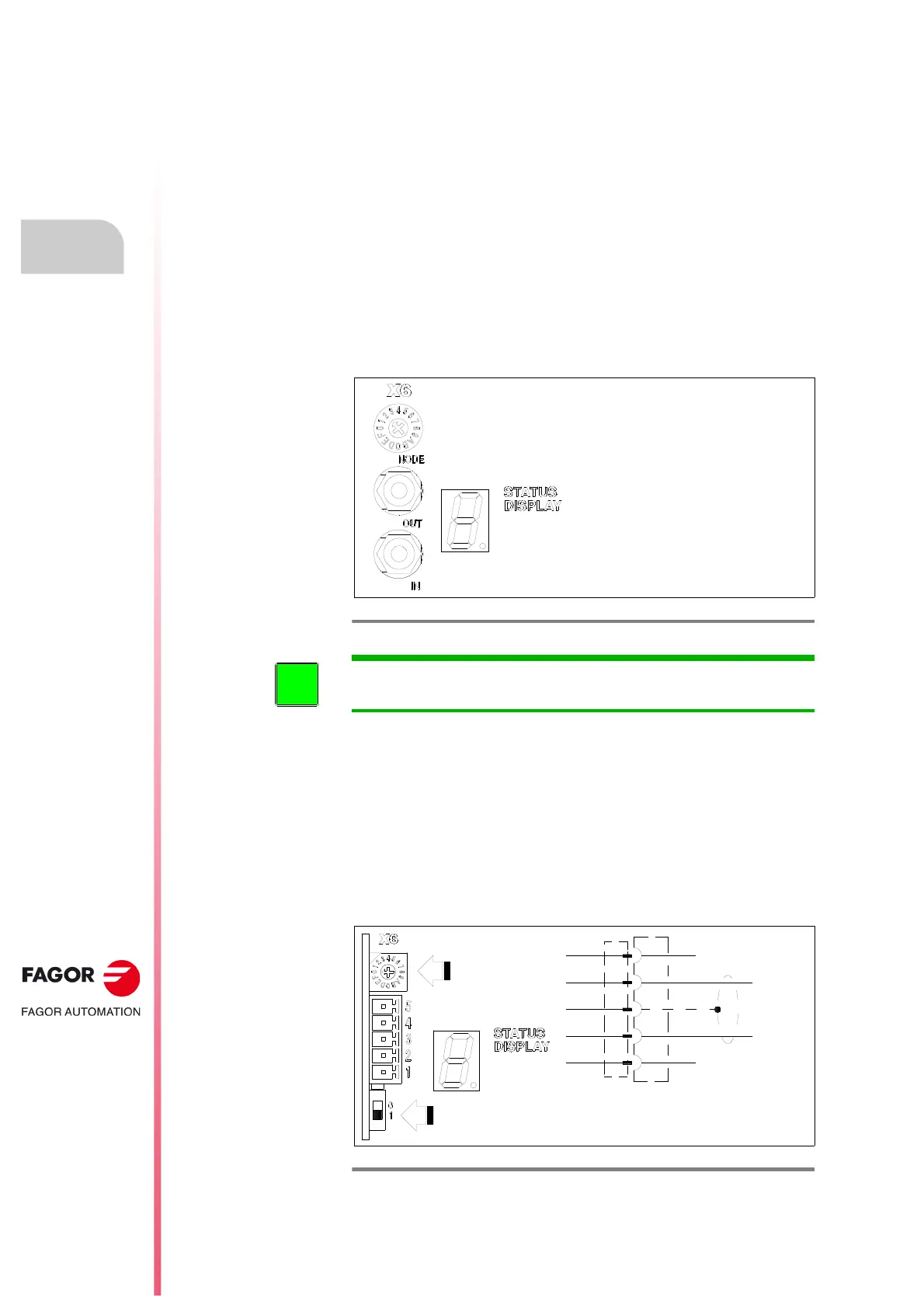
X6. CAN
5-pin female connector where only three pins are connected CANL ·2·,
SHIELD ·3· and CANH ·4· and may be used to connect the module of the
DDS system with the CNC or another master element (ESA panel) that
governs them.
The connection is made with a CAN cable and it has a field bus network
type structure. It will always come with a node selecting rotary switch that
lets identify each drive within the system.
F. H3/71
X6 connector. Emitter-receiver for SERCOS-II transmission.
INFORMATION. Note that on modular “AXD, SPD and MMC” drives, this
connector will always come with connector X5.
F. H3/72
X6 connector. Bus CAN interface.
5
4
3
2
1
NOT CONNECTED
CANH
SHIELD
CANL
NOT CONNECTED
Line terminating resistor ON (1) | OFF (0) selecting switch
NODE
SELECTOR
 Loading...