Power supplies
2.
94
Ref.1912
DDS
HARDWARE
· 64 ·
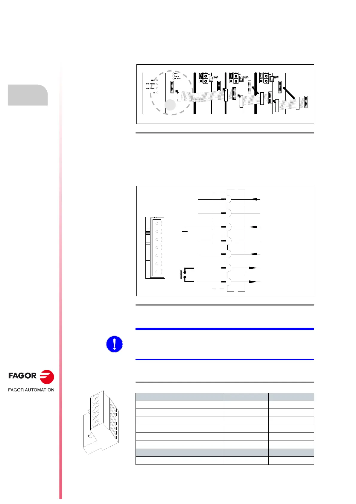
Other connectors
X1 connector
The communication between all the modules that make up the DDS system
is established through connector X1.
A ribbon cable is provided with each module (power supply or drive) for this
connection.
X2 connector
The power supply module may be controlled through X2.
The internal circuits are protected with a 1.25 A fuse.
The following table shows the values for gap, tightening torque, sections and
other data of the plug-in connector for X2.
F. H2/23
Connection of the internal bus between modules through connector X1.
F. H2/24
Control of the power supply module through connector X2.
X2 CONNECTOR
Phoenix 5.00 mm
XPS-25|65
1
2
3
4
ERROR RESET
GND
SYSTEM SPEED
ENABLE
SYSTEM OK
5
6
7
NOT CONNECTED
1
7
NOT CONNECTED
MANDATORY. Remember that the internal circuits of PS-65A non-
regenerative power supplies must be powered by an external 24 V DC
power supply, ·APS-24·; that's why its control connector has three terminals
more than connector X2 of the XPS.
T. H2/19 Plug-in connector for X2. Technical data.
Connector data XPS-25 XPS-65
Nr of poles 7 7
Gap (mm) 5.00 5.00
Min./max. tightening torque (N·m) 0.5/0.6 0.5/0.6
Screw thread M3 M3
Min./max. section (mm²) 0.2/2.5 0.2/2.5
Rated current In (A) 12 12
Wire data
Length to strip (mm) 7 7
 Loading...