Installation
8.
310
· 300 ·
Ref.1912
DDS
HARDWARE
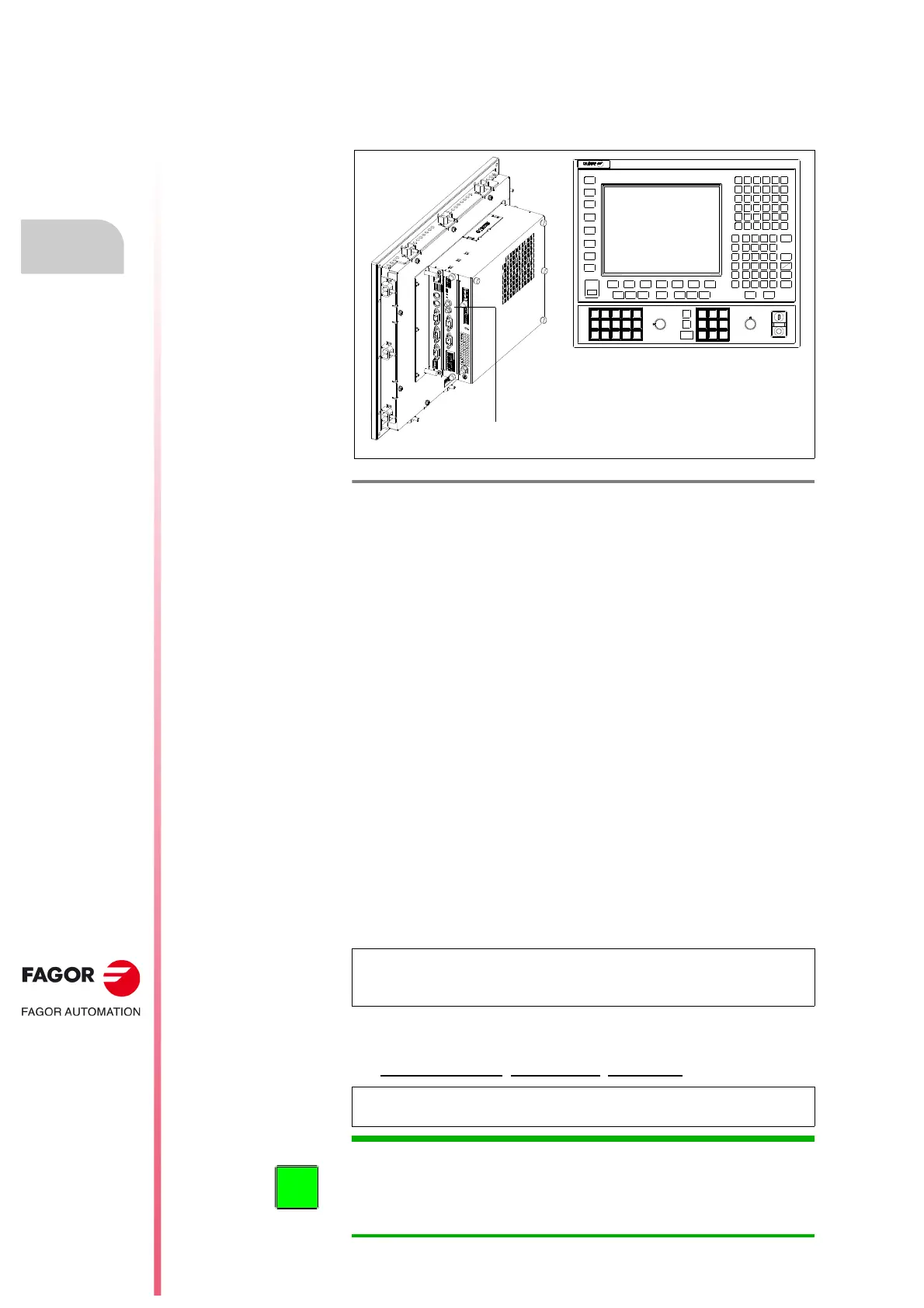
SERCOS connection with a FAGOR 8070 CNC
The FAGOR 8070 CNC is connected to the drives via SERCOS through the
SERCOS DRIVES connector located on the right side of the module. See
figure
.
For further information, see the installation manual of the 8070 CNC.
CAN BUS connection
The ISO 11898 CAN interface is an international standard for digital
communications between CNC's and drives of CNC machines. The
communication protocol is CanOpen according to EN 50325-4.
The CAN communication bus integrates several functions:
It carries the velocity command from the CNC to the drive in digital
format with greater accuracy and immunity against outside disturbances.
It carries the feedback signal from the drive to the CNC.
It communicates the errors and manages the basic control signals of the
drive (enables).
It allows setting, monitoring and diagnosis of the parameters from the
CNC with simple and standard procedures.
Its open standard structure provides compatibility between CNC's and drives
from different manufacturers on the same machine.
The different drives and the CNC are connected through CAN connector (X6)
carried by each drive of the FAGOR catalog (see their front panel) through the
CAN cable. See chapter
7. CABLES in this manual.
It is a tree type connection where the 16-position rotary switch (0-15) of each
drive permits selecting the address of each module integrated in it.
Particular
Differentiate each drive with the 16-position rotary switch “NODE SELECT”
with sequential numbers
(recommended, not required) starting from 1.
F. H8/37
SERCOS connector of the FAGOR 8070 CNC.
NOTE. Remember that it is not possible to use both SERCOS and CAN
interfaces at the same time. The hardware can only be used with one of the
two boards in the drive.
NOTE. The module must be reset in order for any change made on the
rotary switch to be effective.
SERCOS DRIVES
8070 1OK CNC
INFORMATION. The DRIBUSID parameters of the CNC must have the same
ID numbers as the ones assigned by means of the NODE SELECT switch.
See figure
F. H8/28.
If the same motor is to be used as C axis and spindle, the two CNC tables
must have the same value for the DRIBUSID parameter.
 Loading...