Drives
3.
180
Ref.1912
DDS
HARDWARE
· 160 ·
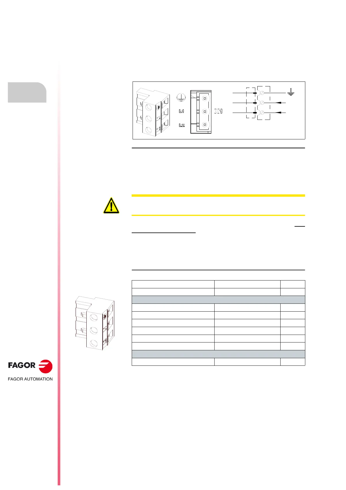
X1 connector
Compact drives internally generate the 24 V DC necessary for the internal
circuits.
In regular operation, this voltage is obtained from the power bus and from
line voltage of the mains when starting up the system.
It is a three-pin connector used to supply from mains the necessary start-up
energy.
The start-up process needs an internal module test prior to supplying
power to the upper terminals. Therefore, bear in mind the following
warning:
Current from mains phases to these lines L1 and L2 must be obtained from
a point before the contactor providing the three - phase power to the upper
connectors of the compact drive.
The following table shows the values for gap, tightening torque (wire entry
holes) and other data regarding the screw-on terminals of the plug-in
connector for X1 according to drive model:
F. H3/113
X1 connector. Line voltage INPUT (2-ph, VAC) from the mains.
1
2
3
L2
L1
LINE VOLTAGE
LINE VOLTAGE
200/240 V AC on ACD/SCD ... -L models
400/460 V AC on ACD/SCD/CMC models
WARNING. This internal power supply must be powered through connector
X1 before carrying out any electrical maneuver.
T. H3/23 Aerial plug-in connector for X1. Technical data.
ACD|SCD|CMC SCD
1.08|1.15|1.25|2.35|2.50 2.75
Connector data
Nr of poles 3 3
Gap (mm) 7.62 7.62
Min./max. tightening torque (N·m) 0.5/0.6 0.5/0.6
Screw thread M3 M3
Min./max. section (mm²) 0.2/2.5 0.2/2.5
Rated current In
(A) 12 12
Connection data
Length to strip (mm) 7 7
 Loading...