Pag. 25
Technical
SCHEMATIC DIAGRAM
BASIC FUNCTION
Pushing a button on the outdoor panel causes the call
signal Cp1, generated in the amplifier, to be sent along
the call line to the corresponding telephone, which produ-
ces the typical tremolo call tone. Upon picking up the
receiver, a switch connects the telephone with the common
audio cables (2 & 6), thus establishing communication
with the outdoor panel from which the call was made.
Pushing the door release button on the telephone joins
wires 1 & 3 of the installation which makes the amplifier
activate the door release of the panel from which the call
was made.
The automatic switcher has two positions: "at rest", which
is the normal condition and "activated".
P1 is the panel which is connected to the telephones when
the automatic switcher is in the "at rest" position, while
P2 is connected when the automatic switcher is in the
"activated" position. So we will call P1 the "at rest" panel
and P2 the "activated" panel.
MATERIAL NEEDED
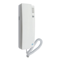
In the dwellings
T1, T2, ...Tn Citymax Telephones Ref. : 8044
In the internal common area
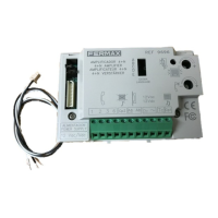
A7 Distributor Power Supply Ref.: 88231
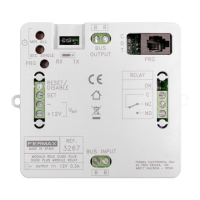
A5 Audio Switcher Ref.: 8811
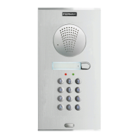
In the street
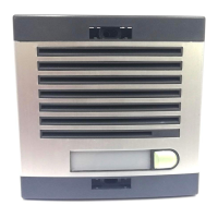
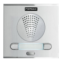
P1 Outdoor panel
Neccessary combination
F1 Electric lock Ref.: 2911
For other types consult catalogue
E 1.4 DOOR PHONE SYSTEM
BUILDING WITH TWO ENTRANCES
OBSERVATIONS
Conversations held throught the "activated" panel limited
to ninety seconds or until a call is made from the other
panel while the conversation being held through the
"at rest" panel will only be cut off if a call is made from the
other panel.
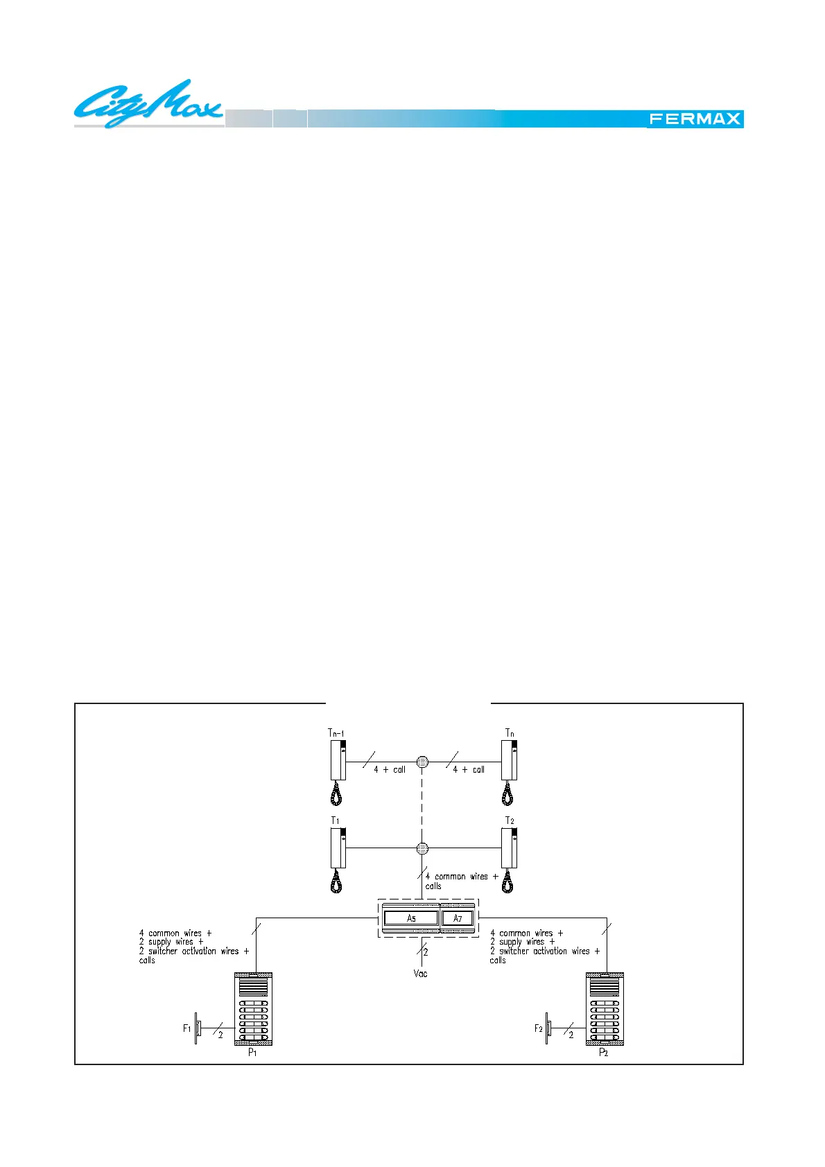
General diagram for a basic door phone installation in a building with two entrances.
To take the switcher to the "activated" position, the current
on the common wire of Cp is made to pass through the
pushbutton common P2 and through the activations
terminals I-K in the switcher. The current on the common
wires of P1 to pass through the activation terminals H-J
would force it into the "rest" position.
However, the switcher will change from "activated" to "at
rest" once 90 seconds have passed.
 Loading...