Pag. 41
Technical
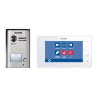
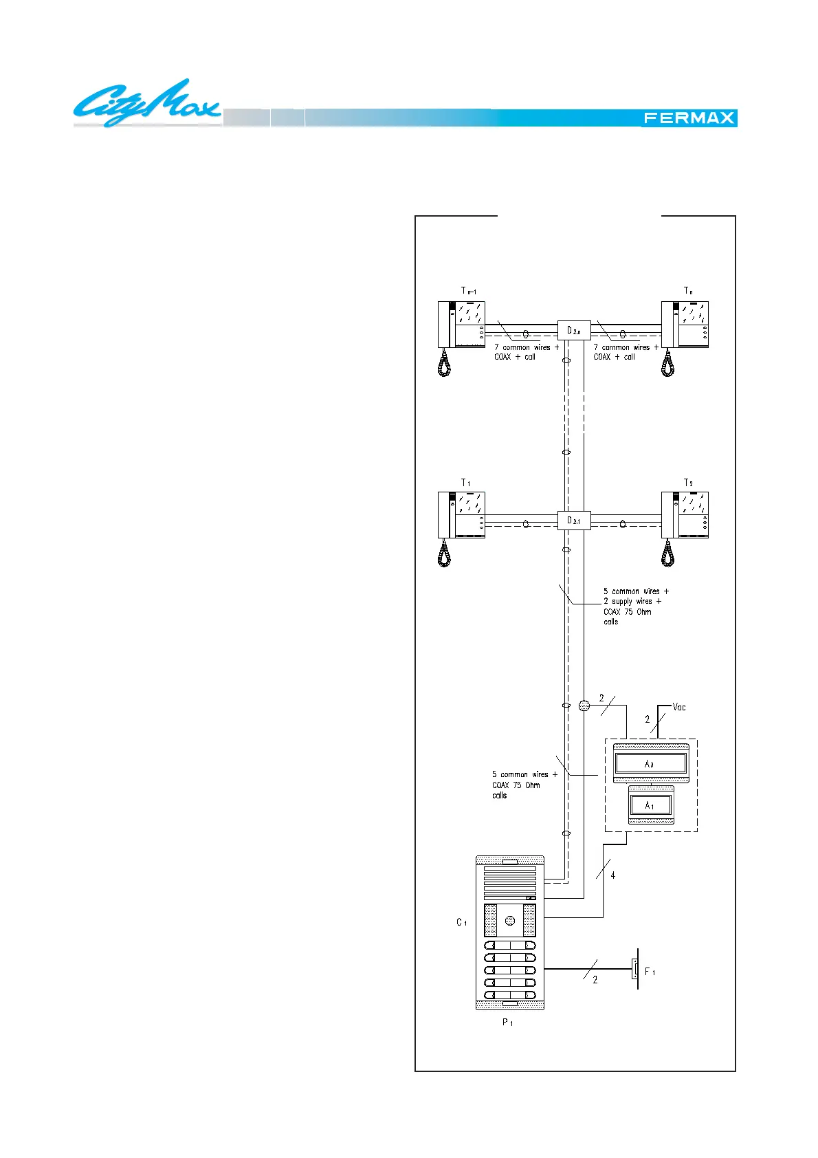
General diagram for a basic video door phone installations in a building with one entrance.
MATERIAL NEEDED
In the dwellings and on the floors
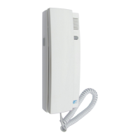
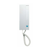
M1, M2,...Mn Citymax Export Monitor Ref.: 8023
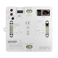
D2.1,... D2.n Video Distributor Ref.: 2448
A distribution of two monitors per floor is assumed
In the communal interior area
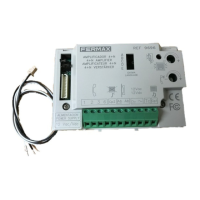
A1 Audio Power Supply Ref.: 8787
A3 Video Power Supply Ref.: 88302
One Video Power Supply for each 60 monitors.
In the street
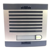
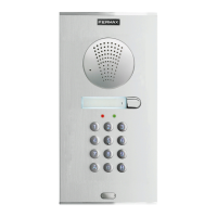
P1 Outdoor Panels
Neccesary combiantion.
Do not forget the telecamera Ref. 8028.
F1 Electric lock Ref.: 2911
For other types consult catalogue.
BASIC FUNCTION
Pushing a determined button on the outdoor panel causes
the call signal Cp1, generated in the amplifier, to be sent
along the call line to the corresponding monitor, which pro-
duces the typical tremolo call tone. At the same time the
screen will switch itself on, showing the image captured by
the telecamera.
Upon picking up the handset, a switch connects the
telephone to the common audio cables (2 & 6), thus
establishing communication with the outdoor panel.
When the door release button on the monitor is pressed
this joins wires 1 and 3 of the installation, which makes the
amplifier activate the door release.
REMEMBER THAT
The connectors Ref. 8033 are supplied seperately from
the monitor.
A telecamera Ref. 8028 has to be installed, therefore a
panel with window must be chosen.
It is neccessary to cut out all the 75 ohm resistors in the
video distributors except the last one. See wiring diagram.
SCHEMATIC DIAGRAM
E 2.1 VIDEO PHONE SYSTEM
BASIC INSTALLATION
 Loading...