Document #50049 Rev. E0 01/22/01 P/N 50049:E0
17
Panel Mounting
2.2.2 MS-9600
The UDACT-F may be mounted to a BRKT-9600 bracket inside the FACP cabinet (see MS-9600 instruction manual)
or mounted remotely in a UBS-1F or ABS-8RF enclosure (see Figure 2-3) and wired according to the diagram below.
Notes for External Applications:
1.
Ferrite cores are recommended for all applications
2.
Recommended wire is 12 AWG to 18 AWG (0.75 to 3.25 mm
2
) twisted wire
3.
Shielded wire is not required (unless mandated by local AHJ)
If shield wire is used, connect only one end of the shield:
✓ shield may be connected to cabinet (earth ground) at fire alarm panel, or
✓ shield may be connected to TB1 Terminal 5 (shield) at UDACT-F as shown in Figure 2-3. Note that the
shield end that is not connected should be insulated to prevent accidental grounding. Do not connect
both ends of the shield under any circumstance, since a ground fault may result.
4.
Conduit is recommended for external wire runs. Consult local building codes
5.
Connect Ground Strap (supplied with ABS-8RF enclosure) from Earth Ground terminal on the UDACT-F to a
solid building earth ground. Conduit alone will not provide a reliable earth ground.
6.
UDACT-F may be located up to 6,000 feet (1,800 m) away from the host control panel
7.
Refer to “Specifications” on page 10, for power requirements
J10
J5
TB3
JP3
JP5
JP6
J10
J11
CUT TO
DISABLE
LOCAL
CHARGER
CUT TO
MONITOR 4XTM
4XTM OPT BD
TB4
TB5
TB6
TB7
TB8
ALARM TRBL SUPV
T
X
R
C
V
D
T
R
G
N
D
I
N
+
O
U
T
+
I
N
–
O
U
T
–
shield
+ –
+24V
GND
RS+
RS–
SHIELD
RS+
RS–
1
2
3
4
5
6
7
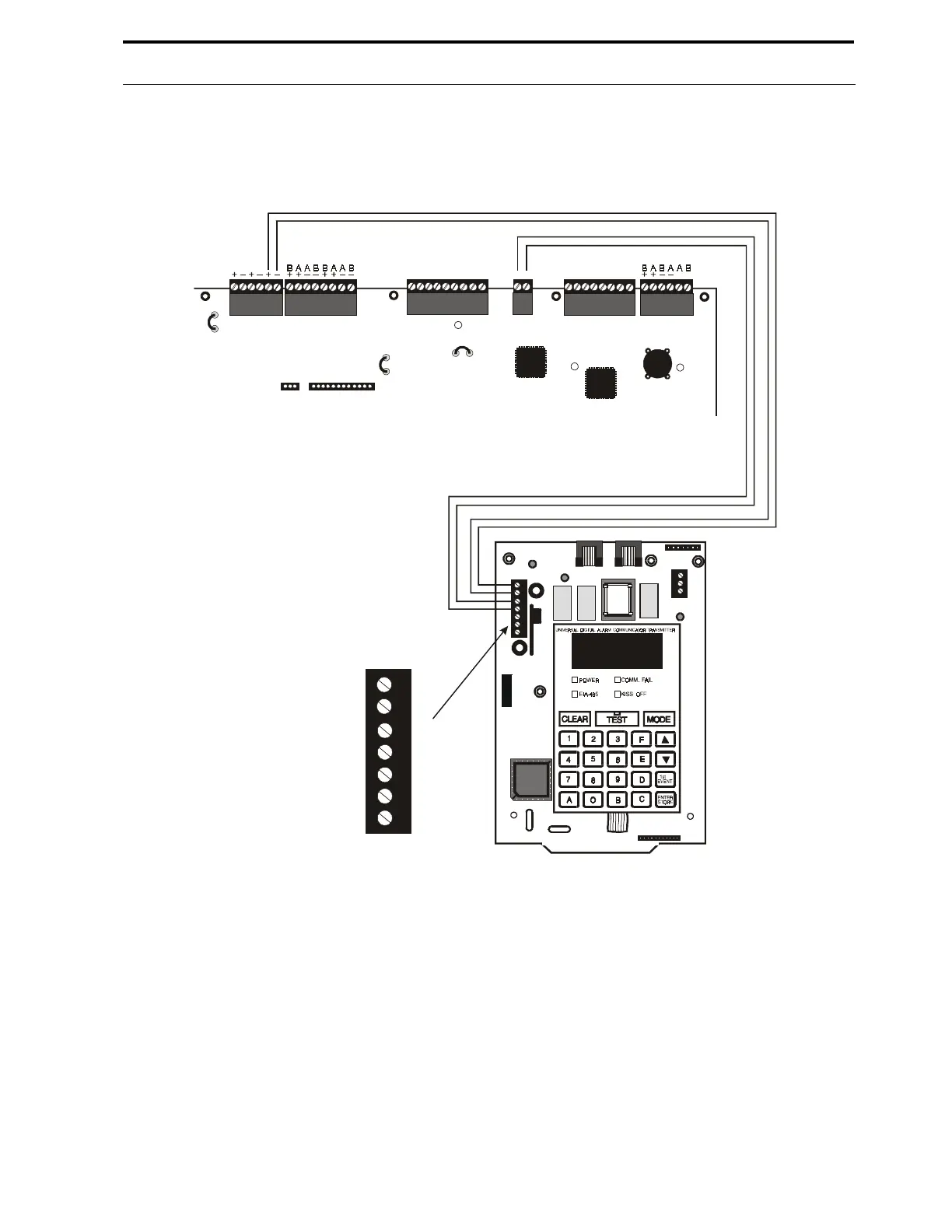
FIGURE 2-4:
UDACT-F Wiring to MS-9600
24 VDC
Nonresettable
Power
MS-9600 Control Panel
 Loading...