EasyManua.ls Logo

Firefly 87510011 User Manual

Firefly 87510011
29 pages
To Next Page IconTo Next Page
To Previous Page IconTo Previous Page
Page #27 background image
27
The NET LED on your Mira module can change color in different situations. Use the following key to
determine the operational status of your module.
Off
Device has no power or has completely failed
Fast flashing green (4 times/sec)
Device is attempting to make initial connection to
the CAN network and good files
Solid green
Device is operating correctly and has seen a CAN
message in the past 5 seconds and good files
Slow flashing green (1 time/sec)
Device was active on the CAN bus but has not seen a
valid message in 5 seconds and good files
Alternating red and yellow
Device has not seen CAN messages in 30 seconds
and good files
Alternating yellow and green
Device is currently active on the CAN bus but has not
seen a CAN message within a 30s interval 2 for more
times since the last power cycle and good files
Solid red
Device has not seen a CAN message in the past 60
seconds and good files
Fast alternating green and blue
(4 times/sec)
Device is attempting to make initial connection to
the CAN network and corrupted files
Solid blue
Device is operating correctly and has seen a CAN
message in the past 5 seconds and corrupted files
Slow alternating green and blue
(1 time/sec)
Device was active on the CAN bus but has not seen a
valid message in 5 seconds and corrupted files
Alternating red and blue
Device has not seen CAN messages in 30 seconds
and corrupted files
Alternating yellow and blue
Device is currently active on the CAN bus but has not
seen a CAN message within a 30s interval 2 or more
times during a power cycle and corrupted files
Solid purple
Device has not seen a CAN message in the past 60
seconds and corrupted files
Flashing white
Device pin is being reset
Solid yellow
Device pin has been reset
Flashing blue
Device does not have a valid application
Flashing red (2 seconds)
Factory test: Red LED
Flashing green (2 seconds)
Factory test: Green LED
Flashing blue (2 seconds)
Factory test: Blue LED
Mira NET LED Status Key
Question and Answer IconNeed help?

Do you have a question about the Firefly 87510011 and is the answer not in the manual?

Firefly 87510011 Specifications

General IconGeneral
BrandFirefly
Model87510011
CategoryAutomobile Accessories
LanguageEnglish

Summary

Lyra Screen Navigation

Home Screen Features

Light Master Control

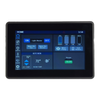
Controls all interior lights at once, with memory function for status.

Climate Control Adjustment

Allows selection of desired set temperature for climate control.

Fluid Tank Readings and Issues

Understanding Fluid Tank Displays

Explains how tank levels are displayed in 5% increments, with Empty and Full thresholds.

Troubleshooting Blue Line Tank Readings

Addresses issues with blue lines under tank readings and provides solutions for initialization.

Battery and Generator Status

Battery Level Indicator

Shows house battery voltage, indicating Green above 12V and Red below 12V.

Generator Controls and Settings

Explains how to start, stop, and set generator hours, including warnings.

Electrical System Overview

Power Source Selection

Details how to select shore power sources (50, 30, 20, or 15 amp).

Auto Gen Start (AGS) Configuration

AGS Trigger Options

Describes triggers like Low Volts or HVAC Load to automatically start the generator.

AGS Timing and Run Time Settings

Covers quiet time, start/stop voltage, run time limits, and retries for the generator.

Lighting Controls

Mood Lighting Presets

Explains how to enable preset lighting schemes like Living Mood or Bedroom Mood.

Climate Control Operations

Climate Control Modes Explained

Details Cool, Heat Pump, Furnace, and Auto modes for temperature management.

Fan Mode Operation

Explains fan operation options (High, Low, Auto) available when HVAC is off.

Slides and Awnings Control

Extending and Retracting Slides/Awnings

Instructions on using EXT and RET buttons to operate slides and awnings.

System Settings Configuration

Mobile App and Network Settings

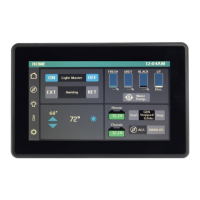
Accessing Vegatouch Mira connection and Network Diagnostics.

Switch Panel and Temperature Units

Navigating to switch panel info and changing temperature units (Fahrenheit/Celsius).

Screen Brightness and Cleaning Mode

Adjusting screen brightness and enabling/disabling cleaning mode.

Floorplan and Time Settings

Displaying floorplan and adjusting time or 24-hour mode.

Vegatouch Mira Mobile App Setup

Network Diagnostics and Faults

Viewing Device and Fault Status

Displays status of Lyra screen, G12 Panel, Aircons, and current system faults.

G12 Panel and Aircon Diagnostics

G12 Output Status

Shows the operational status of each G12 output channel.

Aircon Operational Status

Displays the operational status of the Kitchen and Bedroom Aircons.

Wireless Switch Panel Information

Wireless Switch Status Indicators

Explains color-coded graphics and signal strength for wireless switch panels.

Wireless Switch Pairing Procedure

Troubleshooting Disconnected Switches

Addresses issues with disconnected switches and the need for battery replacement or pairing.

Pairing Process Steps

Step-by-step guide for pairing wireless switch panels with the screen.

Floorplan and Option Selection

Selecting Coach Floorplan

Procedure to select the correct floorplan specific to the coach.

Configuring Coach Options

Selecting available options that are specific to the coach's configuration.

Vegatouch Mira Module Setup

Mira Module Login Information

Locating login credentials for the Mira module on the touchscreen or label.

Downloading and Installing the Mira App

Instructions for downloading and installing the Vegatouch Mira app from app stores.

Connecting to the Mira Module

Steps to scan, select, and authenticate the Mira module using its ID and PIN.

Mobile Device Setup Tips

iOS Bluetooth and Location Services

Enabling Bluetooth and Location Services on iOS devices for Mira connection.

Android Location Services Permissions

Granting location access permissions to the Mira app on Android devices.

Mira App Settings and Information

Temperature Units and System Versions

Configuring temperature units and viewing system information like app version.

Disconnecting and Updating Mira Configuration

How to disconnect from Mira and update its configuration from the cloud.

Diagnostic Tools and Remote Help

Accessing Device List

Displaying a list of currently connected devices within the diagnostic tools.

Enabling Remote Help

Procedure for enabling remote help for technical support, including session ID details.

SSP17 Switch Panel Operation

SSP17 Switch Panel Functionality

Explains how SSP17 panels control lighting and functions, including dimming and operational LEDs.

SSP17 Battery Replacement

Guide for accessing and replacing the 2032 coin cell battery in SSP17 switch panels.

G12 DC Panel Functionality

G12 DC Panel Overview

Describes the G12 panel as the power distribution center and circuit activation.

G12 DC Panel Output Channels

Lists and explains the function of various output channels controlled by the G12 panel.

RV-C Network and NET LED Locations

Understanding NET LED Indicators

Identifies the location of NET LEDs on the G12 Panel and Touchscreen for network status.

Network Status Indicator Key

Panel Network Status Meanings

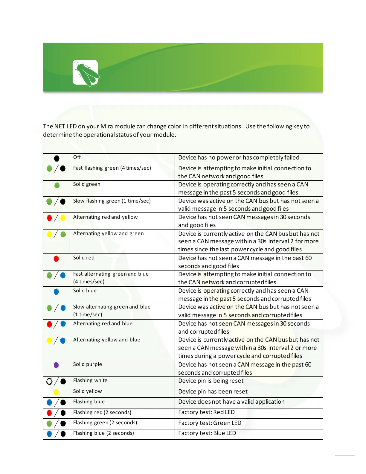
Explains the meaning of various LED states (flashing, solid, colors) for network status.

Mira Module NET LED Status Key

Mira Module LED Status Meanings

Details the operational status of the Mira module based on NET LED color and flashing patterns.

G12 Master Pinout and Load List

G12 High Current Outputs

Lists high current outputs (12A and 6A) with pin assignments and load details.

G12 Thermistors and Inputs

Details thermistor connections and input pin assignments for the G12 panel.

G12 High Current Relays and Half Bridges

Provides information on high current relays and programmable half-bridge outputs.

Network Wiring Diagram

Wiring Diagram Components

Illustrates the network wiring, showing connections between components like gateways and panels.

Network Legend and Symbols

Explains the symbols and legend used in the network wiring diagram for clarity.

Related product manuals