DVC5000 Series
November 1999
2-4
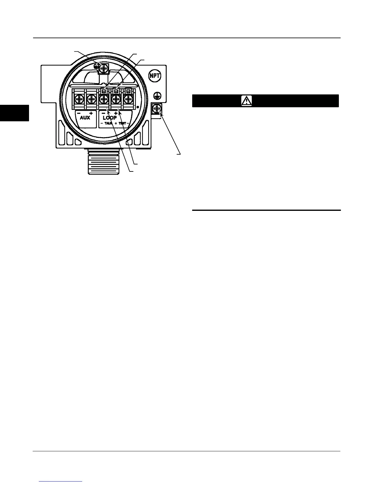
Figure 2-3. DVC5000 Series Digital Valve Controller
Terminal Box
NOTE: THIS TERMINAL BOX IS DIFFERENT THAN PREVIOUS
UNITS. NOTE CHANGE IN POSITION OF LOOP + AND – TERMINALS.
38B6470-B
E0030 / IL
SAFETY GROUND
LOOP–
LOOP+
EARTH GROUND
TALK+
TALK–
4. Connect the safety ground and the earth ground as
shown in figure 2-3. Replace and hand tighten the
terminal box cap. When the loop is ready for startup,
apply power to the control system output card.
WARNING
Personal injury or property damage
can result from the discharge of static
electricity. Connect a 14 AWG (2.08
mm
2
) ground strap between the digi-
tal valve controller and earth ground
when flammable or hazardous gases
are present. Refer to national and lo-
cal codes and standards for ground-
ing requirements.
To avoid static discharge from the
plastic cover, do not rub or clean the
cover with solvents. Clean with a mild
detergent and water only.
nInstallation Check List
Is the instrument correctly mounted on the actuator? If not, see installation
instructions provided with the mounting kit.
Is the feedback linkage properly connected? If not, see installation instructions
provided with the mounting kit.
Is the regulator correctly mounted? If not, perform one of the regulator mounting procedures on
page 2-1.
Is the air supply connected and at proper pressure? If not connect supply as described on page
2-2. Also see specifications on page 5-1.
Is the instrument output connected to the actuator? If not, connect instrument output as
described on page 2-2.
If necessary, is the conduit properly installed? If not, refer to local and national electrical
codes.
j
j
j
j
j
Mounting
Pneumatic Connections and Air Supply
Electrical Connections
j
j
Is the loop wiring properly connected to the LOOP + and – terminals in the terminal box? If not, con-
nect loop wiring as described on page 2-3.
You are ready to perform Initial Setup and Calibration in the next section.
2
 Loading...


