DVC5000 Series
November 1999
4-6
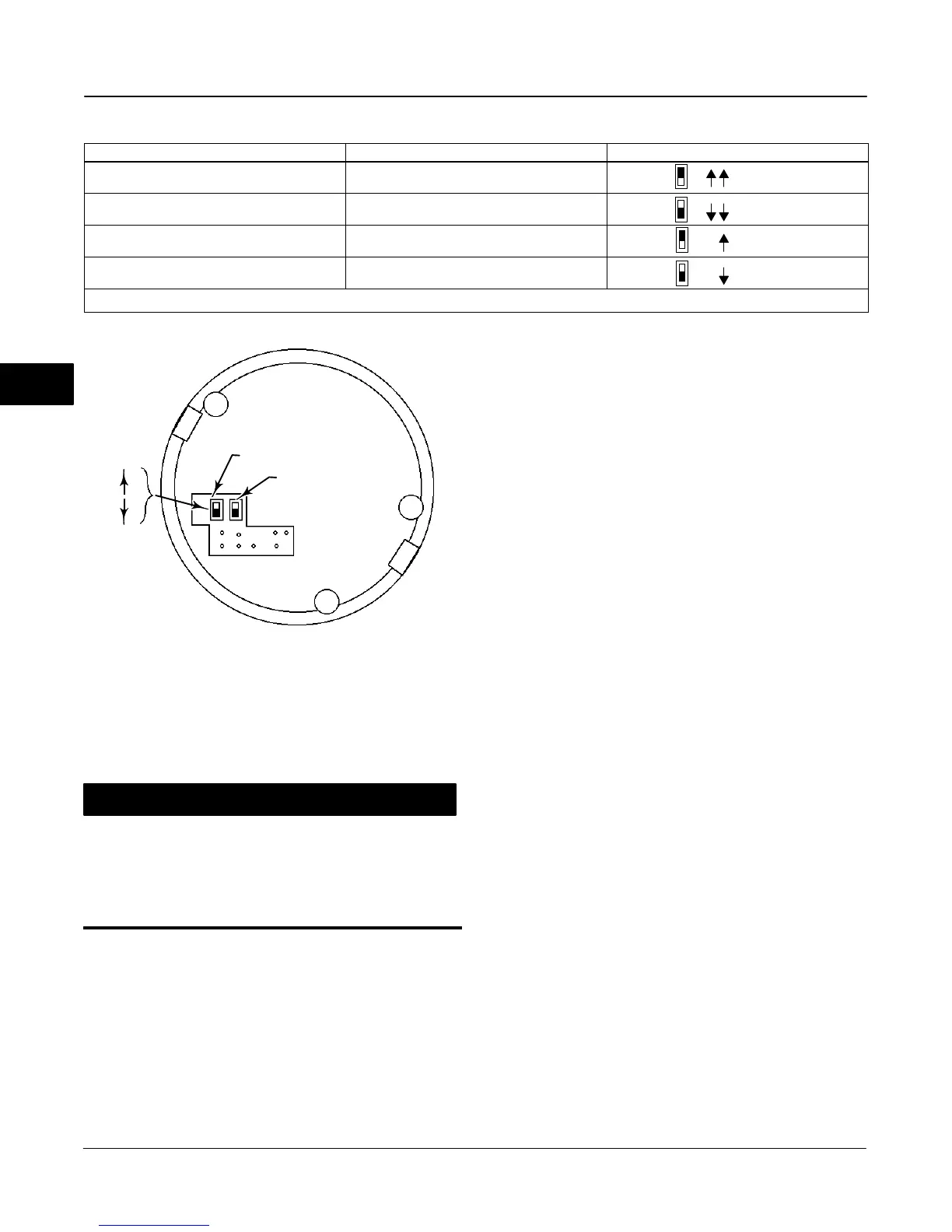
Table 4-1. DIP Switch Configuration
(1)
DIP SWITCH FUNCTION SWITCH SWITCH POSITION
Multidrop Loop Multi-drop
UP
Point-to-Point Loop Multi-drop
DOWN
Auxiliary Terminal, Transmitter Auxiliary
UP (2)
Auxiliary Terminal, Switch Auxiliary
DOWN
1. Refer to figure 4-6 for switch location..
2. Auxiliary terminal, transmitter is available only with the Process PID option.
Figure 4-6. DVC5000 Series Digital Valve Controller
DIP Switch Location
BACK OF PWB ASSEMBLY
SUB-MODULE
MULTI-DROP SWITCH
AUXILIARY SWITCH
UP
DOWN
A6191-2/IL
X
X
NOTE:
X INDICATES PIN REMOVED FOR CONNECTOR KEYING.
CAUTION
Do not use excessive force with the
screwdriver when prying out the relay.
The lip of the notch may break, which
would not allow the O-ring to seal
properly.
Replacing the Pneumatic Relay
1. Ensure the compartment in the module base that
holds the relay is clean.
2. Visually inspect the 0.016-inch hole in the module
base (the fixed bleed on the relay output) to ensure it
is clean and free of obstructions. If cleaning is
necessary, do not enlarge the hole.
3. Apply sealant to four O-rings on the relay.
4. Insert the relay submodule into the module base.
You will feel a slight resistance as the O-rings engage.
No orientation of the relay is necessary.
5. Push on the relay until the O-rings are seated in
their respective bores and the input diaphragm makes
contact with the bottom of the bore. Take care not to
damage the supply port during assembly.
6. If not already installed, attach the coil spring and
O-ring onto the valve plug, and insert the valve plug
through the supply port of the relay.
7. Insert the four screws through the cap. Install the
O-rings on the screws until the O-rings are inside the
counterbored holes and not protruding past the
surface of the cap.
8. Place the Belleville spring in the relay cap, with its
inside diameter contacting the relay cap. Place the
spring washer, with its three fingers pointing up,
against the Belleville spring.
9. Install the relay cap on the module base. As the
relay cap is installed, the spring washer fingers will
grab the relay cap and retain the Belleville spring.
Tighten the screws, in an crisscross pattern, to a final
torque of 20.7 lbfSin (2 NSm).
4
 Loading...


