DVC5000 Series
November 1999
3-4
A6536 / IL
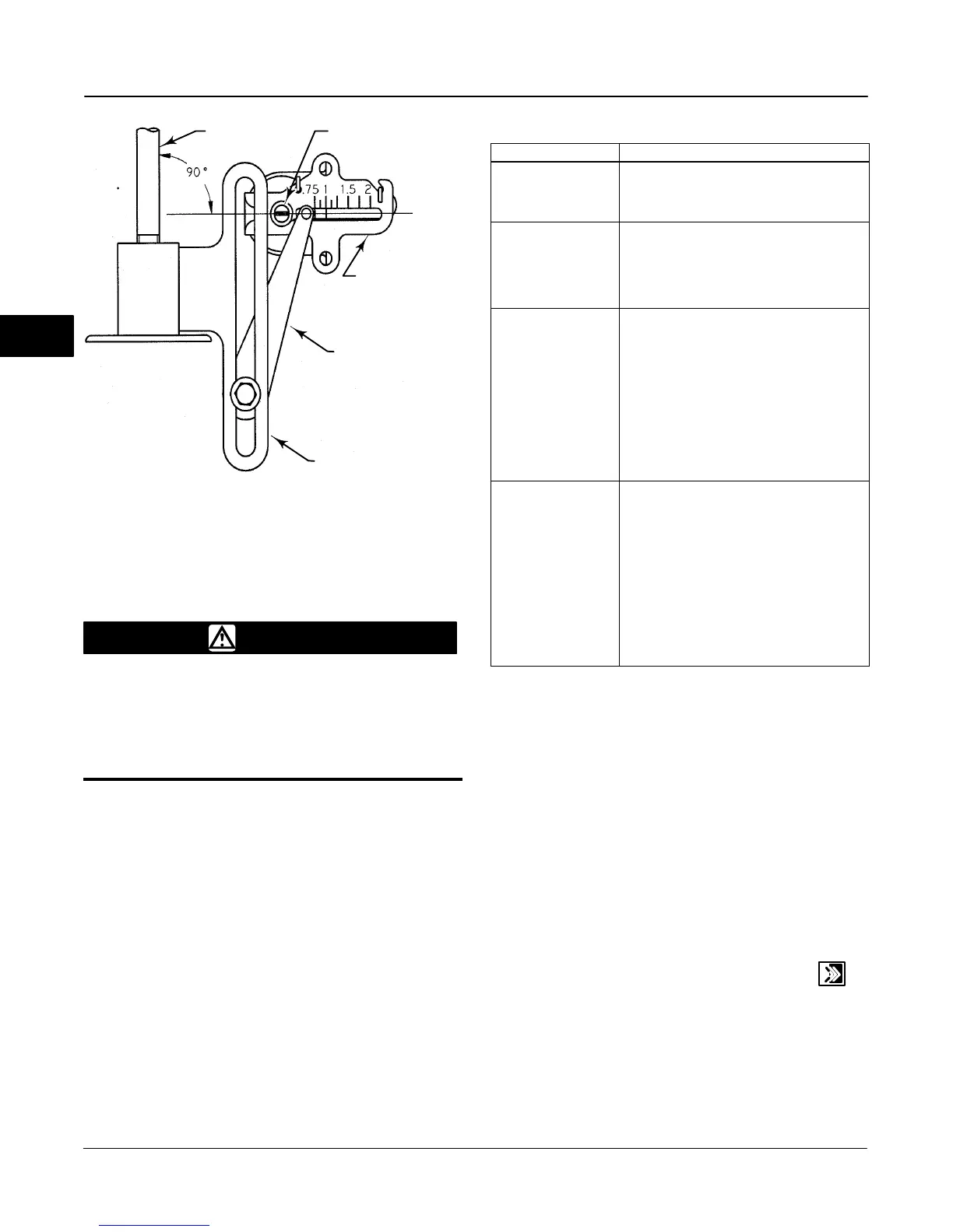
Figure 3-4. Crossover Point
ACTUATOR
STEM
TRAVEL SENSOR SHAFT
FEEDBACK ARM
CONNECTOR ARM
ADJUSTMENT ARM
Auto Calibrate Travel
WARNING
During calibration the valve will move
full stroke. To avoid personal injury
and property damage caused by the
release of pressure or process fluid,
provide some temporary means of
control for the process.
Select Auto Calib Travel then follow the prompts on
the HART Communicator display to automatically
calibrate travel.
1. If the Feedback Connection is Sliding-Stem
Standard, the HART Communicator prompts you to
select the method of crossover adjustment: manual,
last value, or default. Manual adjustment is
recommended for initial travel calibration.
2. When prompted by the HART Communicator,
make the crossover adjustment by adjusting the
current source until the feedback arm is 90° to the
actuator stem, as shown in figure 3-4.
3. The remainder of the auto-calibration procedure is
automatic. After completing auto travel calibration, the
HART Communicator prompts you to place the
instrument In Service and verify that the travel
properly tracks the current source.
Table 3-3. Auto Calibrate Travel Error Messages
Error Message Possible Problem and Remedy
Input current must
exceed 3.8 mA for
calibration.
The analog input signal to the instrument
must be greater than 3.8 mA. Adjust the
current output from the control system or the
current source to provide at least 4.0 mA.
Place Out Of Service
and ensure Calibrate
Protection is disabled
before calib.
The Instrument Mode must be Out of Service
and the Protection must be None before the
instrument can be calibrated. For information
on changing instrument mode and protection,
see Instrument Mode and Configuration
Protection in this section.
Calibration Aborted.
An end point was not
reached.
The problem may be one or the other of the
following:
1. The tuning set selected is too low and the
valve does not reach an end point in the
allotted time. Press the Hot Key, select
Stabilize/Optimize then Increase Response
(selects next higher tuning set).
2. The tuning set selected is to high, valve
operation is unstable and does not stay at an
end point for the allotted time. Press the Hot
Key, select Stabilize/Optimize then Decrease
Response (selects next lower tuning set).
Invalid travel value.
Check travel sensor
and feedback arm
adjustments, and inst
supply press. Then,
repeat Auto Calib.
Verify proper mounting by referring to the
appropriate mounting instructions.
Verify instrument supply pressure by referring
to the specifications in the appropriate
actuator instruction manual.
Verify travel sensor adjustment by performing
the appropriate Travel Sensor Adjust
procedure in the FIELDVUE DVC5000 Series
Digital Valve Controller Instruction Manual –
Form 5335.
Making the crossover adjustment with the
valve positioned at either end of its travel will
also cause this message to appear.
If the unit does not calibrate, refer to table 3-3 for error
messages and possible remedies.
If after completing auto setup and auto calibration the
valve cycles or overshoots, or is unresponsive, you
can improve operation by selecting Stabilize/Optimize
from the Auto Setup menu. For additional information,
refer to Stabilizing or Optimizing Valve Response in
this section.
Stabilizing or Optimizing Valve
Response
If after completing initial setup and auto calibration the
valve seems slightly unstable or unresponsive, you
can improve operation by pressing the Hot Key
and selecting Stabilize/Optimize, or select
Stabilize/Optimize from the Auto Setup menu.
To stabilize valve operation, select Decrease
Response. This selects the next lower tuning set (e.g.,
F to E). To make the valve more responsive, select
Increase Response. This selects the next higher
tuning set (e.g., F to G).
3
 Loading...


