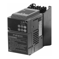
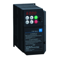
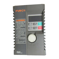
Driving 400 V series motor
If a thermal relay is installed in the path between the inverter and the motor to protect
the motor from overheating, the thermal relay may malfunction even with a wiring
length shorter than 50 m. In this situation, add an output circuit filter (option) or lower
the carrier frequency (Function code F26: Motor sound (Carrier frequency)).
If the motor is driven by a PWM-type inverter, surge voltage that is generated by
switching the inverter component may be superimposed on the output voltage and may
be applied to the motor terminals. Particularly if the wiring length is long, the surge
voltage may deteriorate the insulation resistance of the motor. Consider any of the
following measures.
- Use a motor with insulation that withstands the surge voltage.
- Connect an output circuit filter (option) to the output terminals (secondary circuits) of
the inverter.
- Minimize the wiring length between the inverter and motor (10 to 20 m or less).
Braking resistor terminals, P and DB
1) Connect terminals P and DB of a braking resistor (option) to terminals P and DB on the main
circuit terminal block.
2) Arrange the inverter and braking resistor to keep the wiring length to 5 m or less and twist the
two wires or route them together in parallel.
Main circuit power input terminals, L1/R, L2/S, and L3/T (for three-phase voltage input) or
L1/L and L2/N (for single-phase voltage input)
1) For safety, make sure that the molded case circuit breaker (MCCB) or magnetic contactor
(MC) is turned off before wiring the main circuit power input terminals.
2) Connect the main circuit power supply wires (L1/R, L2/S and L3/T or L1/L and L2/N) to the
input terminals of the inverter via an MCCB or residual-current-operated protective device
(RCD)/earth leakage circuit breaker (ELCB)*, and MC if necessary.
It is not necessary to align phases of the power supply wires and the input terminals of the
inverter with each other.
* With overcurrent protection
It is recommended that a magnetic contactor be inserted which can be manually
activated.
This is to allow you to disconnect the inverter from the power supply in an emergency
(e.g., when the protective function is activated) so as to prevent a failure or accident
from causing the secondary problems.

 Loading...


