9. Function Code Tables
Function codes enable the FVR-Micro of inverters to be set up to match your system requirements.
Each function code consists of a 3-letter alphanumeric string. The first letter is an alphabet that
identifies its group and the following two letters are numerals that identify each individual code in the
group. The function codes are classified into seven groups: Fundamental Functions (F codes),
Extension Terminal Functions (E codes), Control Functions (C codes), Motor 1 Parameters (P codes),
High Performance Functions (H codes), Application Functions (J codes) and Link Functions (y
codes). To determine the property of each function code, set data to the function code.
(This manual only shows F functions, refer to the instruction on website for more functions,)
Changing, validating, and saving function code data when the motor is running
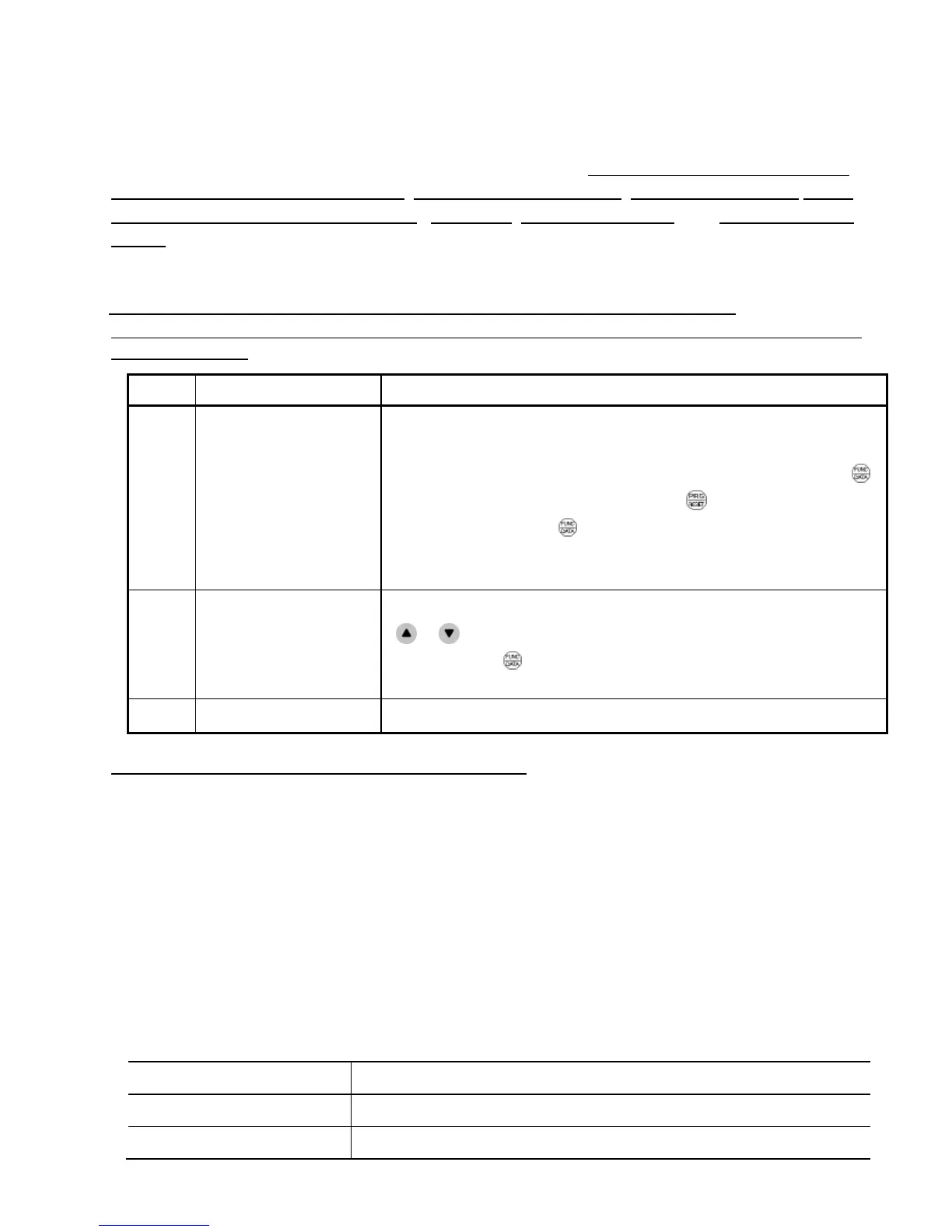
Function codes are indicated by the following based on whether they can be changed or not when the
inverter is running:
Notation
Change when running Validating and saving function code data
Y*
Possible
If the data of the codes marked with Y* is changed, the change
will immediately take effect; however, the change is not saved
into the inverter's memory. To save the change, press the
(Function/Data) key. If you press the (Program/Reset) key
without pressing the (Function/Data) key to exit the current
state, then the changed data will be discarded and the previous
data will take effect for the inverter operation.
Y
Possible
The data of the codes marked with Y can be changed with the
or keys regardless of whether the motor is running or not.
Pressing the (Function/Data) key will make the change
effective and save it into the inverter's memory.
Using negative logic for programmable I/O terminals
The negative logic signaling system can be used for digital input terminals and transistor output
terminals by setting the function code data specifying the properties for those terminals. Negative
logic refers to the inverted ON/OFF (logical value 1 (true)/0 (false)) state of input or output signal. An
active-ON signal (the function takes effect if the terminal is short-circuited.) in the normal logic
system is functionally equivalent to active-OFF signal (the function takes effect if the terminal is
opened.) in the negative logic system. An active-ON signal can be switched to active-OFF signal,
and vice versa, with the function code data setting.
To set the negative logic system for an input or output terminal, enter data of 1000s (by adding 1000
to the data for the normal logic) in the corresponding function code.
Example: "Coast to a stop" command BX assigned to any of digital input terminals [X1] to [X3] using
any of function codes E01 through E03.
Function code data BX
7 Turning BX ON causes the motor to coast to a stop. (Active ON)
1007 Turning BX OFF causes the motor to coast to a stop. (Active OFF)
 Loading...


