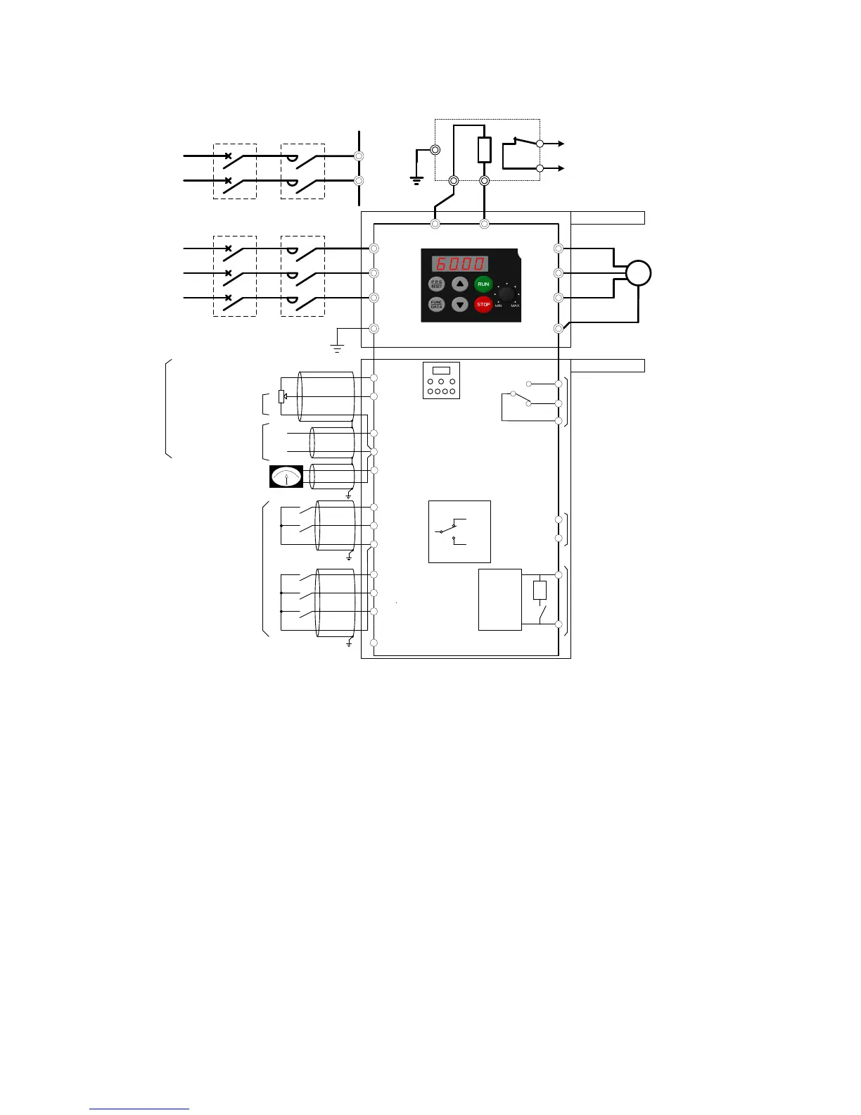
7. Connection diagram in operation by external signal inputs
Voltage Input
0 to 10 VDC
[Y1]
[Y1E]
[DX+]
Analog input
Analog Meter
[DX-]
Current Input
+4(0) to +20 mADC
[FWD]
[REV]
[CM]
[X1]
[X2]
[X3]
[PLC]
RJ-45
[FMA]
Digital input
[13]
[12]
[C1]
30A
30B
30C
Alarm output
(for any fault)
Transistor Output
Power supply
Single-phase
200 to 240V
50/60Hz
R
[11]
(+)
(-)
3
2
1
Power supply to
potentiometer
RS-485
Communication port
*With a built-in
resistor switch
SINK
SOURCE
L1/L
L2/N
MC (Note 2)
MCCB or
RCD/ELCB
(Note 1)
Control Circuit
Main Circuit
(Note 5)
(Note 6)
ELCB : Earth Leakage Circuit Braker
MC : Magnetic Contactor
MCCB : Molded Case Circuit Braker
RCD : Residual-current- operated
Protective Device
U
V
W
Grounding termical (Note 7)
G
M
Motor
Power supply
Three-phase
380 to 480V
50/60Hz
G
L1/R
L2/S
L3/T
MC (Note 2)
MCCB or
RCD/ELCB
(Note 1)
Grounding termical
P DB
DBR (Dynamic Braking Resistor)
P
DB
2
1
[CM]
[THR]
(Note 4)
nstall a recommended molded case circuit breaker (MCCB) or a residual-current-
perated protective device (RCD)/earth leakage circuit breaker (ELCB) (with overcurrent
ection) in the primary circuit of the inverter to protect wiring. Do not use an MCCB or
RCD/ELCB whose capacity exceeds the recommended rated current.
magnetic contactor (MC) should, if necessary, be mounted independent of the MCCB or
cut off the power fed to the inverter. MCs or solenoids that will be installed close to
the inverter require surge absorbers to be connected in parallel to their coils.
he THR function can be used by assigning "9" (External alarm) to any of terminals [X1] to
[X3],[FWD] or [REV] (function code E01 to E03, E98, or E99).
ency can be set by connecting a frequency setting device (external potentiometer)
etween terminals [11], [12] and [13] instead of inputting voltage signal (0 to +10 VDC or 0 to
+5VDC) between terminals [12] and [11].
For the wiring of the control
circuit, use shielded or twisted wires. When shielded wires are
, connect the shields to earth. To prevent malfunction due to noise, keep the control
circuit wiring away from the main circuit wiring as far as possible (recommended: 10 cm or
longer),
and never set them in the same wire duct. When crossing the control circuit wiring with
the main circuit wiring, set them at right angles.
 Loading...


