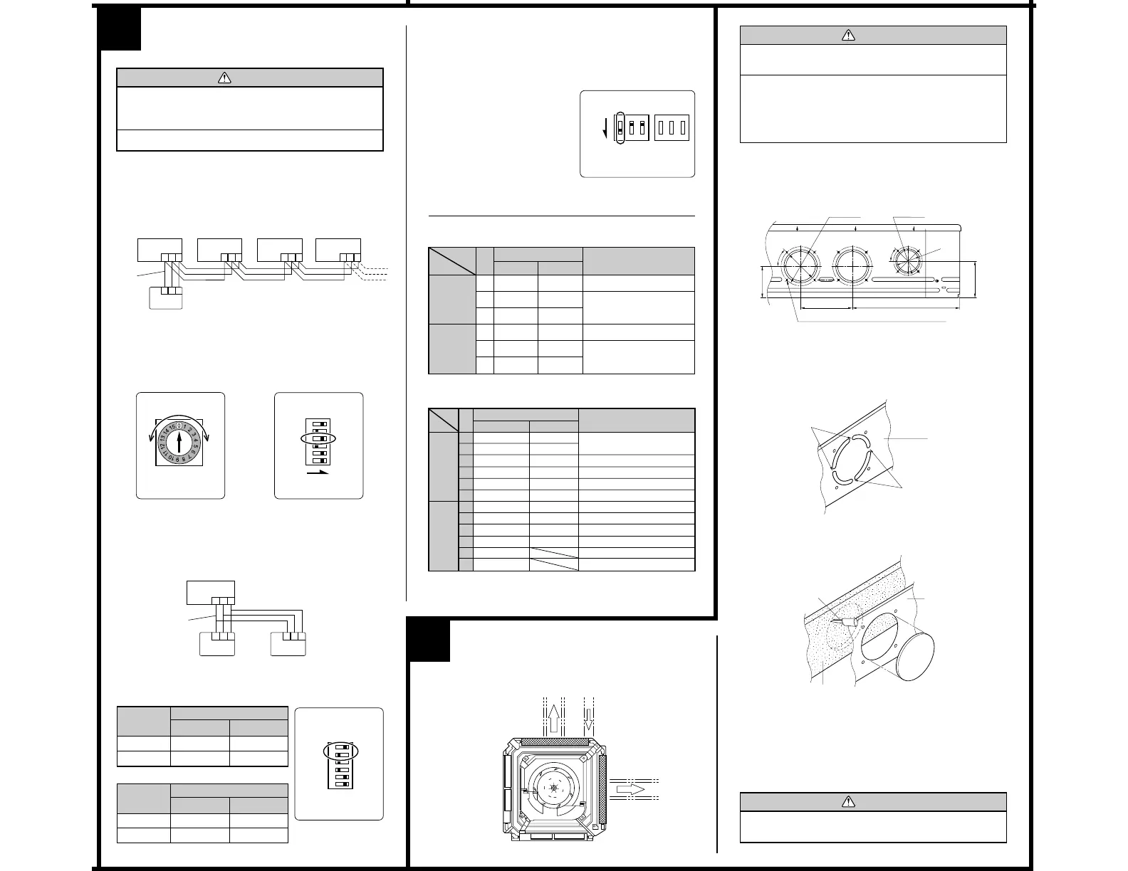
Indoor unit No. 0 Indoor unit No. 1 Indoor unit No. 2 Indoor unit No. 3
Remote
controller
wire
Remote
controller
(2) Rotary switch setting (indoor unit)
Set the unit number of each indoor unit using the rotary switch on the
indoor unit circuit board.
The rotary switch is normally set to 0.
(3) DIP switch setting (remote controller)
Change DIP switch 1 No. 3 on the remote controller from OFF to ON.
Indoor unit
Rotary Switch
Remote controller
DIP Switch 1
2. DUAL REMOTE CONTROLLERS (OPTIONAL)
Two separate remote controllers can be used to operate the indoor units.
(1) Wiring method (indoor unit to remote controller)
(2) DIP switch setting (remote controller)
Set the remote controller DIP switch 1 No. 1 and 2 according to the
following table.
Number of
remote
controllers
Master unit
1 (Normal)
2 (Dual)
ON
OFF
OFF
OFF
DIP-SW 1 No. 1
DIP-SW 1 No. 2
Remote controller
DIP Switch 1
Number of
remote
controllers
Slave unit
1 (Normal)
2 (Dual)
–
ON
–
ON
DIP-SW 1 No. 1
DIP-SW 1 No. 2
SW3
1 2 3
1 2 3
1 2 3
ONOFF
1
2
3
4
5
6
ON
1 2 3 1 2 3 1 2 3
1 2 3
1 2 3
ONOFF
1
2
3
4
5
6
NO.
SW state
Detail
OFF ON
1 Invalidity Validity
★
Auto restart setting
2— —
★
Temperature correction
3— —
★
setting
1—
★
— Remote controller setting
2—
★
—
Air flow setting
3—
★
—
DIP-Switch 1
● Indoor unit
● Remote controller
[DIP-SWITCH SETTING]
DIP-Switch 4
OPENING THE DUCT
CONNECTION HOLE
Distribution duct
Distribution duct
Fresh air
CAUTION
1 When performing hole opening work, be careful not to
damage the drain pan.
2 When connecting the distribution duct, to make the air
flow easily, block the outlet port with the blower cover
insulation as shown by the hatched lines in the figure.
For the blocking direction, refer to blower cover insu-
lation figure.
1. DIMENSION
Screw position and connection hole which are fresh air duct and distribu-
tion duct.
12-ø3.3 self tapping screw holes (for 4 mm)
2. DISTRIBUTION DUCT AND FRESH AIR DUCT
HOLE PROCESSING
Use the distribution duct hole and fresh air duct hole by removing the
insulation material as shown below.
Cut
Cut
Cabinet
• Cut off the part (Cabinet) indicated by the arrow in the figure with
nippers, needle nose pliers, etc.
1. GROUP CONTROL SYSTEM
A number of indoor units can be operated at the same time using a single
remote controller.
(1) Wiring method (indoor unit to remote controller)
Cabinet
Knife
Insulation
(Inner box)
10
3. AUTO RESTART
• When the air conditioner power was temporarily turned off by a power
failure etc., it restarts automatically after the power recovers.
(Operated by setting before the power failure)
The auto restart function can be
canceled.
(1) DIP switch setting (indoor unit)
Change the DIP switch (SW1-1)
on the indoor unit circuit board
from ON to OFF. The auto restart
function will be canceled.
Indoor unit
O
F
F
1
2
3
OFF
SW1
O
F
F
1
2
3
SW4
DIP Switch
9
SPECIAL INSTALLATION
METHODS
CAUTION
1 When setting the rotary switch and DIP switches, do
not touch any other parts on the circuit board directly
with your bare hands.
2 Be sure to turn off the main power.
Remote
controller
wire
Indoor unit
Master
unit
Slave
unit
• Open the holes and cut the insulation with a knife.
* Be careful not to damage the internal parts.
* Be careful not to cut yourself on the cutout in the metal plate.
* Please remove the insulation (inner box) left over after cutting.
• Connect the distribution duct.
* When mounting the duct, block the gap so that there is no cold air leakage.
* Insulate the duct and cut connection.
CAUTION
The air conditioner cannot take in fresh air by itself. When
connecting a fresh air duct, always use a duct fan.
Remote
controller
P. D 120 P. D 88
97 mm
160 mm (6-5/16")
334.2 mm (13-5/32")
113 mm
(4-7/16")
(★: Factory setting)
ON
★
Multiple units
Cooling only model
★ Validity
Validity
Invalidity
Invalidity
★ Invalidity
Invalidity
Detail
Dual remote controller setting
Group control setting
Model setting
AUTO changeover setting
Memory Backup setting
THERMO SENSOR button setting
ENERGY SAVE button setting
Horizontal airflow direction and swing button setting
Vertical airflow direction and swing button setting
Cannot be used.
Cannot be used.
No.
1
2
3
4
5
6
1
2
3
4
5
6
OFF
★
★ One unit
★
Heat & cool model
Invalidity
★ Invalidity
★ Validity
★ Validity
Validity
★ Validity
★ Fixed at OFF
★ Fixed at OFF
SW state
DIP-
switch 1
DIP-
switch 2
 Loading...