2
INSTALLING DRAIN PIPE
CAUTION
Install the drain pipe in accordance with the instructions
in this installation instruction sheet and keep the area warm
enough to prevent condensation. Problems with the pip-
ing may lead to water leaks.
NOTE: Install the drain pipe.
••
••
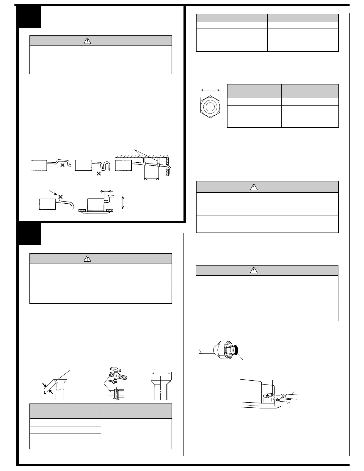
• Install the drain pipe with downward gradient (1/50 to 1/100) and so
there are no rises or traps in the pipe.
••
••
• Use general hard polyvinyl chloride pipe (VP25) [outside diameter
32 mm (1-1/4")] and connect it with adhesive (polyvinyl chloride) so
that there is no leakage.
••
••
• When the pipe is long, install supporters.
••
••
• Do not perform air bleeding.
••
••
• Always heat insulate the indoor side of the drain pipe.
••
••
• When desiring a high drain pipe height, rise it up to 800 mm (31") or
less from the ceiling within a range of 150 mm (6") from the body. A
rise dimension over this range will cause leakage.
Max. 800 mm (31")
Rise
Tra p
Supporter
1.5 to 2.0 m (5 to 6.5 ft)
Air bleeding
150 mm (6") or less
3
CONNECTING THE PIPING
CAUTION
1 Do not use mineral oil on flared part.
Prevent mineral oil from getting into the system as this
would reduce the lifetime of the units.
2 While welding the pipes, be sure to blow dry nitrogen
gas through them.
1. FLARING
(1) Cut the connection pipe to the necessary length with a pipe cutter.
(2) Hold the pipe downward so that cuttings will not enter the pipe and
remove the burrs.
(3) Insert the flare nut (always use the flare nut attached to the indoor
and outdoor units respectively) onto the pipe and perform the flare
processing with a flare tool.
Use the special R410A flare tool, or the conventional flare tool.
Check if [L] is flared uniformly
and is not cracked or scratched.
B
Die
A
Pipe
6.35 mm (1/4 in.)
9.52 mm (3/8 in.)
12.70 mm (1/2 in.)
15.88 mm (5/8 in.)
0 to 0.5 mm
(0 to 0.0197 in.)
Pipe outside diameter
Dimension A
Flare tool for R410A, clutch type
Width across flats
6.35 mm (1/4 in.)
9.52 mm (3/8 in.)
12.70 mm (1/2 in.)
15.88 mm (5/8 in.)
9.1 mm (0.3583 in.)
13.2 mm (0.5197 in.)
16.6 mm (0.6536 in.)
19.7 mm (0.7756 in.)
Pipe outside diameter
Dimension B
When using conventional flare tools to flare R410A pipes, the dimension
A should be approximately 0.5 mm (1/32") more than indicated in the
table (for flaring with R410A flare tools) to achieve the specified flaring.
Use a thickness gauge to measure the dimension A.
Pipe outside
diameter
Width across flats
of Flare nut
6.35 mm (1/4 in.)
9.52 mm (3/8 in.)
12.70 mm (1/2 in.)
15.88 mm (5/8 in.)
17 mm (0.6693 in.)
22 mm (0.8661 in.)
26 mm (1.0236 in.)
29 mm (1.1417 in.)
CAUTION
1 To prevent breaking of the pipe, avoid sharp bends.
Bend the pipe with a radius of curvature of 150 mm (6")
or over.
2 If the pipe is bent repeatedly at the same place, it will
break.
The pipes are shaped by your hands. Be careful not to collapse them.
Do not bend the pipes in an angle more than 90
°.
When pipes are repeatedly bend or stretched, the material will harden,
making it difficult to bend or stretch them any more. Do not bend or
stretch the pipes more than three times.
2. BENDING PIPES
To prevent gas leakage, coat the flare
surface with alkylbenzene oil (HAB).
Do not use mineral oil.
Indoor unit
Connection pipe
(Liquid)
Connection pipe
(Gas)
(2) Centering the pipe against port on the indoor unit, turn the flare nut
with your hand.
3. CONNECTION PIPES
Indoor unit
(1) Detach the caps and plugs from the pipes.
CAUTION
1 Be sure to apply the pipe against the port on the in-
door unit correctly. If the centering is improper, the flare
nut cannot be tightened smoothly. If the flare nut is
forced to turn, the threads will be damaged.
2
Do not remove the flare nut from the indoor unit pipe
until immediately before connecting the connection pipe.
 Loading...