3-3. No operation (Power is on)
Forecast of cause
Setting/ Connection failure
External cause
Electrical components defective
Check point 1. Check indoor and outdoor installation condition
• Indoor unit:
– Check incorrect wiring between indoor unit and remote controller.
– Check if there is an open cable connection.
• Are these indoor unit, outdoor unit, and remote controller suitable model numbers to connect?
-> If there is some abnormal condition, correct it by referring to the installation manual and “DESIGN
& TECHNICAL MANUAL”.
↓
Turn off the power and check correct followings.
• Is there loose or removed communication line of indoor unit and outdoor unit?
↓
Check point 2. Check external cause at indoor and outdoor (Voltage drop or Noise)
• Instant drop: Check if there is a large load electric apparatus in the same circuit.
• Momentary power failure: Check if there is a defective contact or leak current in the power sup-
ply circuit.
• Noise: Check if there is any equipment causing harmonic wave near electric line. (Neon bulb or
electric equipment that may cause harmonic wave)
Check the complete insulation of grounding.
↓
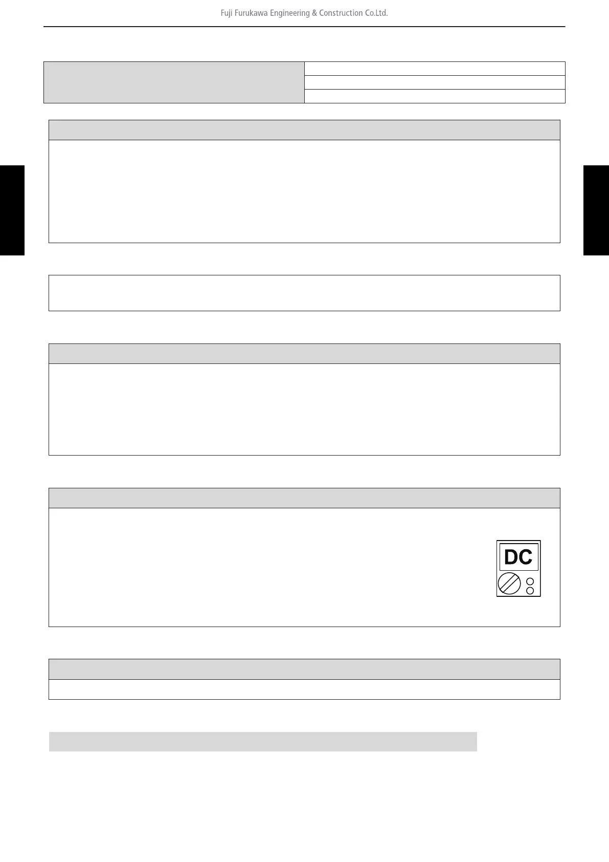
Check point 3. Check wired remote controller and controller PCB
Check voltage at CNC01 (terminal 1—3) of main PCB.
(Power supply to remote controller)
• If it is DC 13 V, remote controller is failure. (The controller PCB is normal)
-> Replace remote controller.
• If it is DC 0 V, controller PCB is failure. (Check the remote controller once
again)
-> Replace controller PCB.
↓
Check point 4. Replace main PCB
If check point 1 to 3 do not improve the symptom, change main PCB.
↓
End
3-3. No operation (Power is on) - (03-32) - 3. Troubleshooting without error code
TROUBLESHOOTING
TROUBLESHOOTING
 Loading...