5.3 Self Test
27
5.3.2 Scanner unit
Follow the procedure below to test the scanner unit.
1. Press [MENU/ESC] to open the fourth page of the user menu.
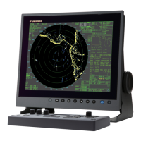
Fig.5-4 4/4 of user menu
2. Select “Scanner test” and press ►. The test starts and the result is displayed.
* Long range = about 24.0 rpm
Medium range = about 31.0 rpm
Short range = about 41.0 rpm
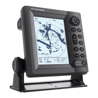
Fig.5-5 Scanner test result
Note that ANTENNA STATUS is always NG (0) at the first test. Carry out scanner test
again for correct reading.
ANTENNA STATUS is only the result of power-on flag test.
▲
RADAR SETUP ►
SCANNER TEST …
[MENU/ESC]: Exit.
▲
▼
(4/4)
ANTENNA STATUS
HEADING
BEARING
TUNE:
TOTAL ON TIME
TOTAL TX TIME
: OK (xx)
: OK
: OK
(24.0 rpm)*
: 00000 h
: 00000h
INPUT NMEA
RMA RMB RMC BWC GLL GGA
MTW VTG VHW XTE VBW DPT
DBK DBS DBT HDT HDG HDM
BWR GLC GTD MWV ZDA
[MENU/ESC]: Exit.
Status code
8 bit data is displayed b
 Loading...