Chapter 1 Circuit Description
1
1.1 General
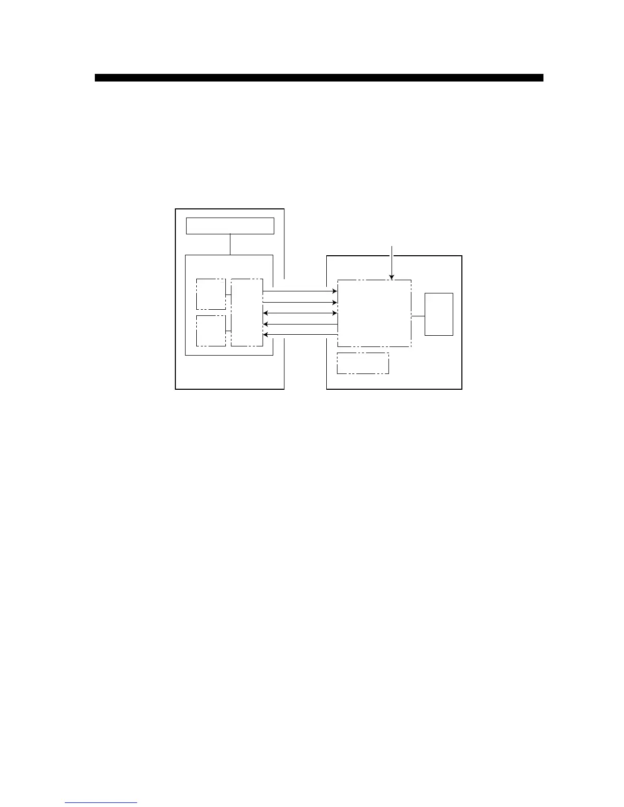
The CPUs in the display and scanner units communicate each other via RS-422 interface. The
control data, such as Gain, STC and tuning data, is sent from the display unit to the scanner unit
in serial.
DU
LCD
BP HD
H.C
H.C
INT
I/F
MD
IF
IF
Fig.1-1 Simplified Block Diagram
The trigger pulse is generated on DU board in the display unit and sent to the modulator on MD
board in the scanner unit. The modulated signal triggers the magnetron and high frequency
pulses are transmitted from the radiator. The target echo received by the radiator is
frequency-converted by the MIC. 60 MHz IF signal is amplified in the scanner unit and then sent
to the display unit. DU board in the display unit processes video signal to show target echoes on
the LCD display.
Bearing pulse (BP) and heading signal (HD) are also delivered to the display unit from the
scanner unit.
Radiator
Scanner unit
Transceiver
LCD
Trigger
Display unit
MD
Board
Video signal
IF
Board
INT
Board
Communication (H.C)
Ship’s mains
PNL Board
BP/HD
DU Board
Ship’s mains (H.C)
Signal processor
& power supply
 Loading...