4. INSTALLATION
4-2
4.2 Mounting Considerations
Install the units in compliance with IEC 62616 Annex A and IMO MSC.128(75).
• Locate the units away from exhaust pipes and vents.
• Make sure the location has good ventilation.
• Mount the units where shock and vibration are minimal.
• Locate the units away from the equipment that generates electromagnetic fields,
such as a motor or generator.
• Allow space as indicated in the outline drawings, to facilitate maintenance and ser-
vicing.
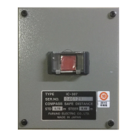
• Follow the compass safe distances indicated on page iii to prevent interference to
a magnetic compass.
• Keep the units away from direct sunlight to prevent heat that can build up inside their
cabinets. The LCD of the Main Alarm Panel BR-510 can darken if put in direct sun-
light.
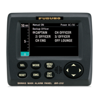
• For the Main Alarm Panel, the optimal viewing distance is 0.5 m. Select a location
within that distance.
• For the Timer Reset Panel:
• Locate the units on the bridge where a proper lookout is available.
• The means of activating the reset functions shall be easily accessible from the
conning position, the workstation for navigating and maneuvering, and the work-
station for monitoring and the bridge wings (if applicable).
• The 1st stage audible alarm shall be audible from all operational positions on the
bridge where the OOW may reasonably be expected to be stationed.
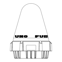
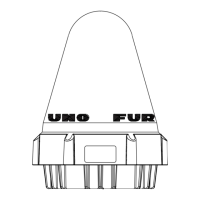
• For the Motion Detector:
• The motion detector monitors movement of personnel on the bridge. The moni-
toring range is as shown below when the sensor is mounted on the overhead at
a height of two meters. The sensor, consisting of multiple optical elements, is a
passive infrared sensor that senses the movement of heat sources (personnel).
The movement of a heat source is not detected when it is within the receiving
beam of an optical element, and movement may not be detected in the fore-aft
direction. The farther distance of the heat source from the motion detector may
not be detected unless its movement is large, because the beamwidth increases
with distance.
• For the Flash Beacon, the flashing indication shall be visible from all operational
positions on the bridge where the OOW may reasonably be expected to be sta-
tioned.
MOTION
DETECTOR
BR-500
BNWAS MOTION DETECTOR
FURUNO
2m
40°
1.6m
Receiving beam
 Loading...