 Loading...
Do you have a question about the Furuno FCV-600L and is the answer not in the manual?
| Power Output | 600 W |
|---|---|
| Frequency | 50/200 kHz |
| Waterproof Rating | IPX6 |
| Transmit Power | 600 W |
| Frequency Range | 50/200 kHz |
| Operating Temperature | -15°C to +55°C |
| Display Type | LCD |
| Power Supply | 12-24 VDC |
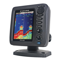
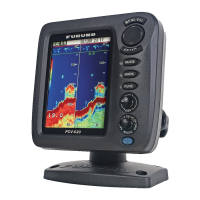
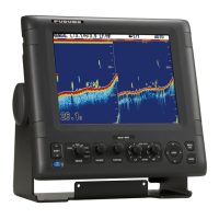
Details the key capabilities and components of the FCV-600L sounder.
Describes the function of each control on the display unit's front panel.
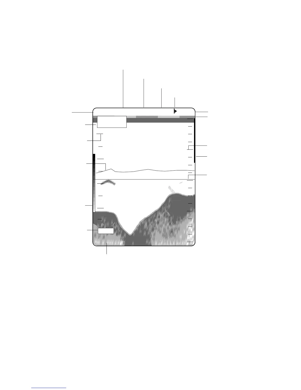
Explains the various indicators and markers displayed on the sounder screen.
Details the procedure for powering the unit on and off.
Explains how to adjust the display's tone and brightness settings.
Describes how to choose from the different available display modes.
Guides on selecting the appropriate depth range for viewing underwater conditions.
Provides instructions on adjusting the receiver's sensitivity for optimal echo display.
Explains how to use automatic modes for gain and range adjustment.
Details how to adjust the speed at which scan lines update on the screen.
Describes how to remove unwanted weak echoes from the display.
Explains the use of the VRM for measuring depths to objects.
Details the A-scope display for estimating fish schools and bottom composition.
Outlines the functions available within the user menu for adjustments.
Provides methods to reduce interference from other electronic equipment.
Explains how to reduce low-level noise and clutter on the display.
Guides on customizing background and echo colors for better visibility.
Details the setup and operation of various audible and visual alarms.
Explains how to highlight specific echo colors with a white marker.
Describes individual gain adjustments for 50 kHz and 200 kHz transducers.
Explains how to access and navigate the optional mode menu.
Introduces the three system menus for configuring various unit settings.
Guides on activating a demo mode to showcase features without a transducer.
Details how to adjust the bottom echo detection circuit for stable readings.
Explains the function of Time Varied Gain for echo compensation.
Describes how to adjust echo levels when gain controls are insufficient.
Defines the zero line representing the transducer's position.
Explains how fish schools are displayed and interpreted on the screen.
Details how bottom echoes are displayed and what they indicate about bottom composition.
Describes causes and appearance of surface noise and aeration on the display.
Lists items for regular maintenance to ensure performance and longevity.
Provides instructions for safely cleaning the display screen.
Explains how to maintain the transducer face for optimal sensitivity.
Details the procedure and precautions for replacing the unit's fuse.
Offers solutions for common operational problems and issues.
Describes the procedure for testing ROM, RAM, color bar, and keyboard.
Explains how to test the display's color reproduction capabilities.
Guides on resetting all menu settings to their factory defaults.
Lists general technical specifications like frequency, power, and sensitivity.
Details specifications related to the display unit, including size and color capabilities.
Specifies the input and output data formats, primarily NMEA.
Outlines the unit's power requirements and consumption.
Lists operating environmental limits such as temperature and humidity.
Describes the color specifications for the unit's panel and chassis.