16
3.4 INSPECTION OF EACH BOARD
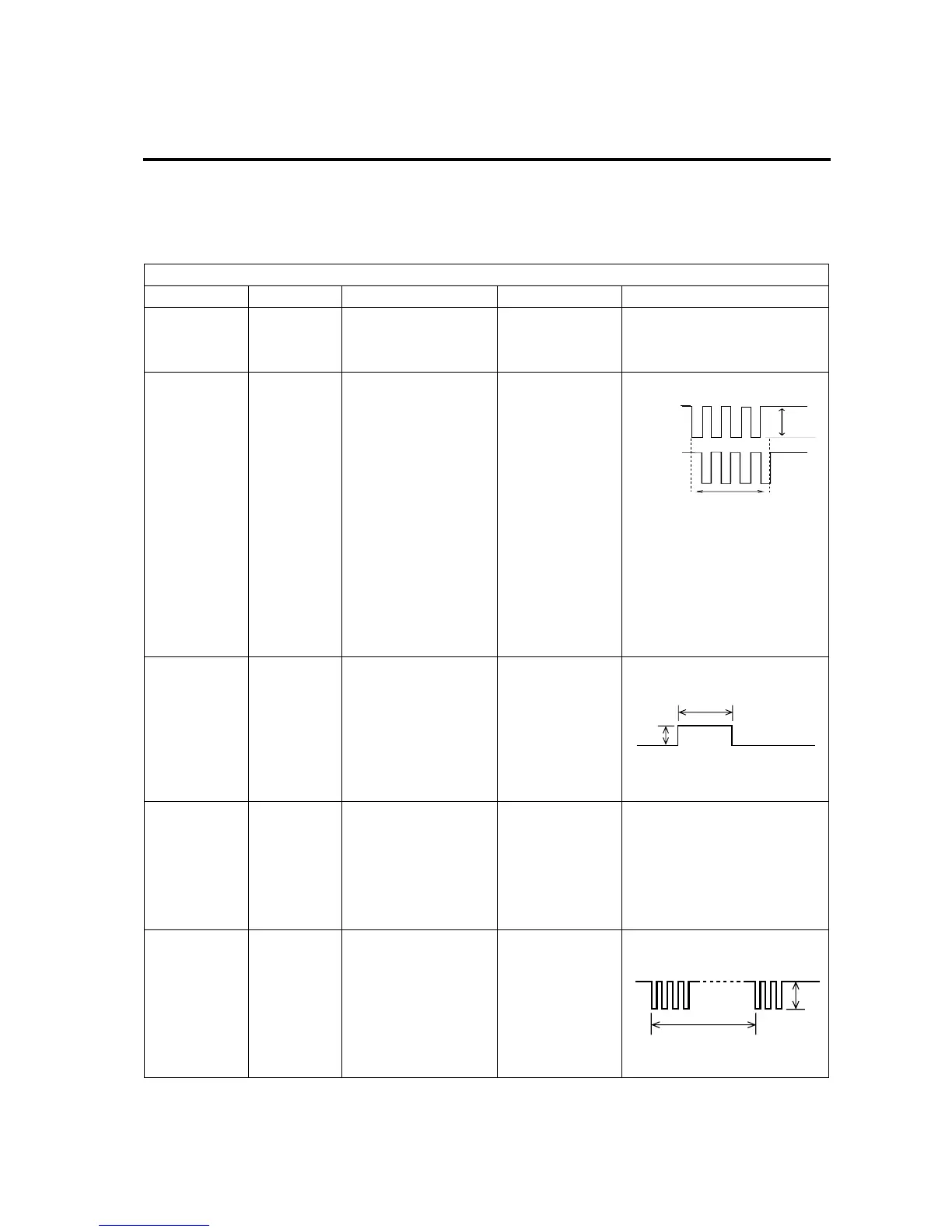
Board/Unit : MAIN board (02P6236)
Signal In/Out Measuring Points Measured by Rating/Remarks
FREQ Output ANLG Board
J4, #21 and GND
Oscilloscope 50 kHz :
H
200 kHz :
L
(L=0 V, H=5 V)
TX0/TX1 Output ANLG Board
J4, #29 and GND
J4, #30 and GND
Oscilloscope
1) TX0 and TX1 have
opposite phase each
other.
2) Frequency is equal to the
TX frequency.
KP Output MAIN Board
J6, #3 and J6, #4
Oscilloscope
Same timing as TX0 and
TX1
GAIN Output ANLG Board
J4, #22 and GND
Multimeter Changes according to gain
setting
Setting
0
: about 1.9 V
Setting
5
: about 3.1 V
Setting
10
: about 3.8 V
IEC61162
TD-A , TD-B
Output ANLG Board
J4, #17 and #18
Oscilloscope
Changes depending on range setting
5V
Changes depending on range setting
5V
about 1 sec
Changes depending on data
3.4 INSPECTION OF EACH BOARD

 Loading...