9
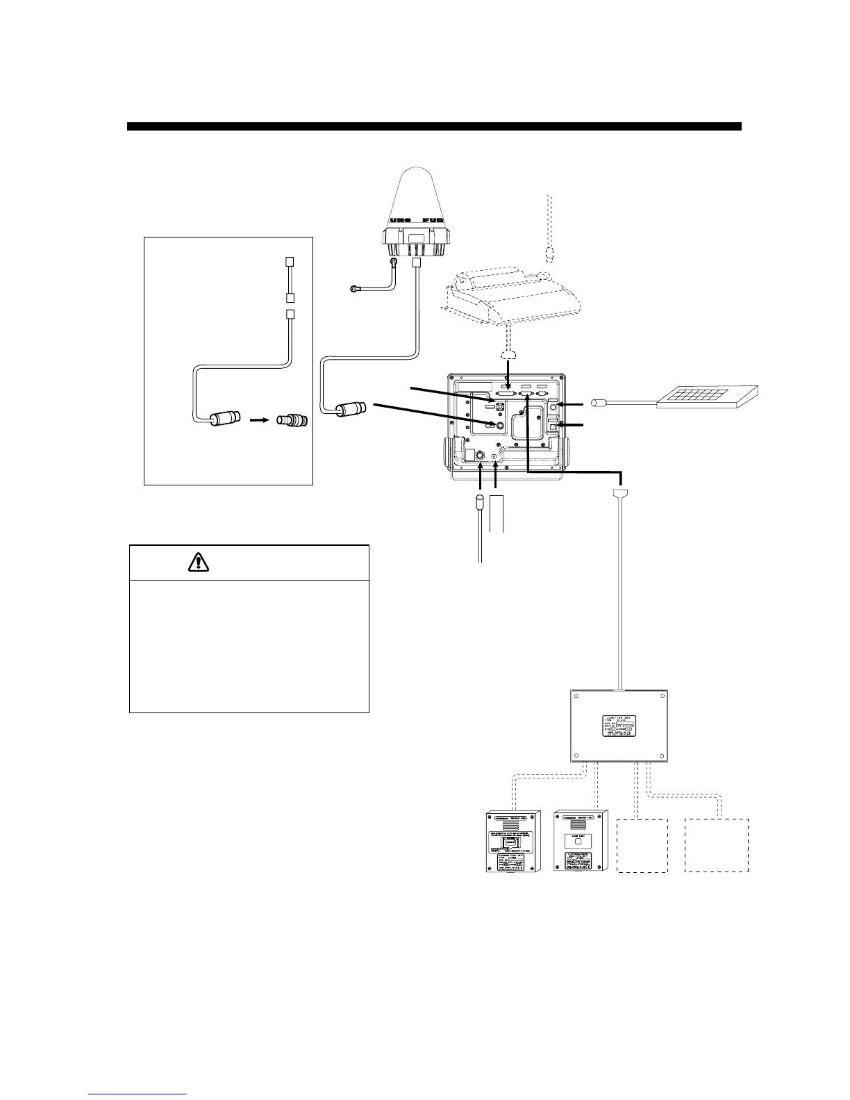
2. WIRING
Power supply
24 VDC
1.2 m
Printer
PP-510
Copper strap
Ground wire
Distress alert/
Received call
unit
IC-305
TP5FBAW-5DFB,
30 m (No armor)
Connector at both
ends
0.34 m
Mini keyboard
G84-4100PPAUS
5D-FB-CV-NP, 30 m
8D-FB-CV, 50 m
12D-SFA-CV, 100 m
Connector at one end
For cable w/armor
DMC-5#
Navigator
CO-SPEVV-SB-C 0.2x5p
(option)
or TTYCS-4
(Japanese
Industrial
Standards)
LAN cable
(10BaseT, local supply)
Remove the cover to use.
DGPS
Connector N-P-5DFB
N-P-8DFB
N-P-12DSFA
(Supplied, local arrangement)
24 VDC
VCTF-0.75x3C
(5 m)
TNCP-NJ
connector
(Supplied)
16S0184,
3 m
Junction Box
IC-315
*
*
*
*
*
*
*
Alarm unit
IC-306
The terminal unit is shipped with a 15 A
fuse in its power cable. This fuse is for use
with a 12 VDC power supply.
For a 24 VDC power supply, replace the
fuse with a 7A fuse (supplied). Attach the
"7A" label to the fuse holder on the power
cable. Use of a wrong fuse can damage the
equipment.
CAUTION
MJ-A3SPF0018-050Z
#: When connecting with the Distress Message
Controller DMC-5, set the DMC-5's function for
"SES (EGC)," in the SET UP EGC/SES menu,
referring to chapter 7 "SYSTEM SETTINGS" in the
operator's manual for DMC-5 (OME-5540).
Further, connect a jumper wire between TB5-#1
and TB5-#3 on the DMC-5.
Cable Assy.
TPA5FB0.4NJ5FBA-5DFB
Wiring of FELCOM 15
 Loading...