4. INSTALLATION OF GPS BOARD (OPTION)
19
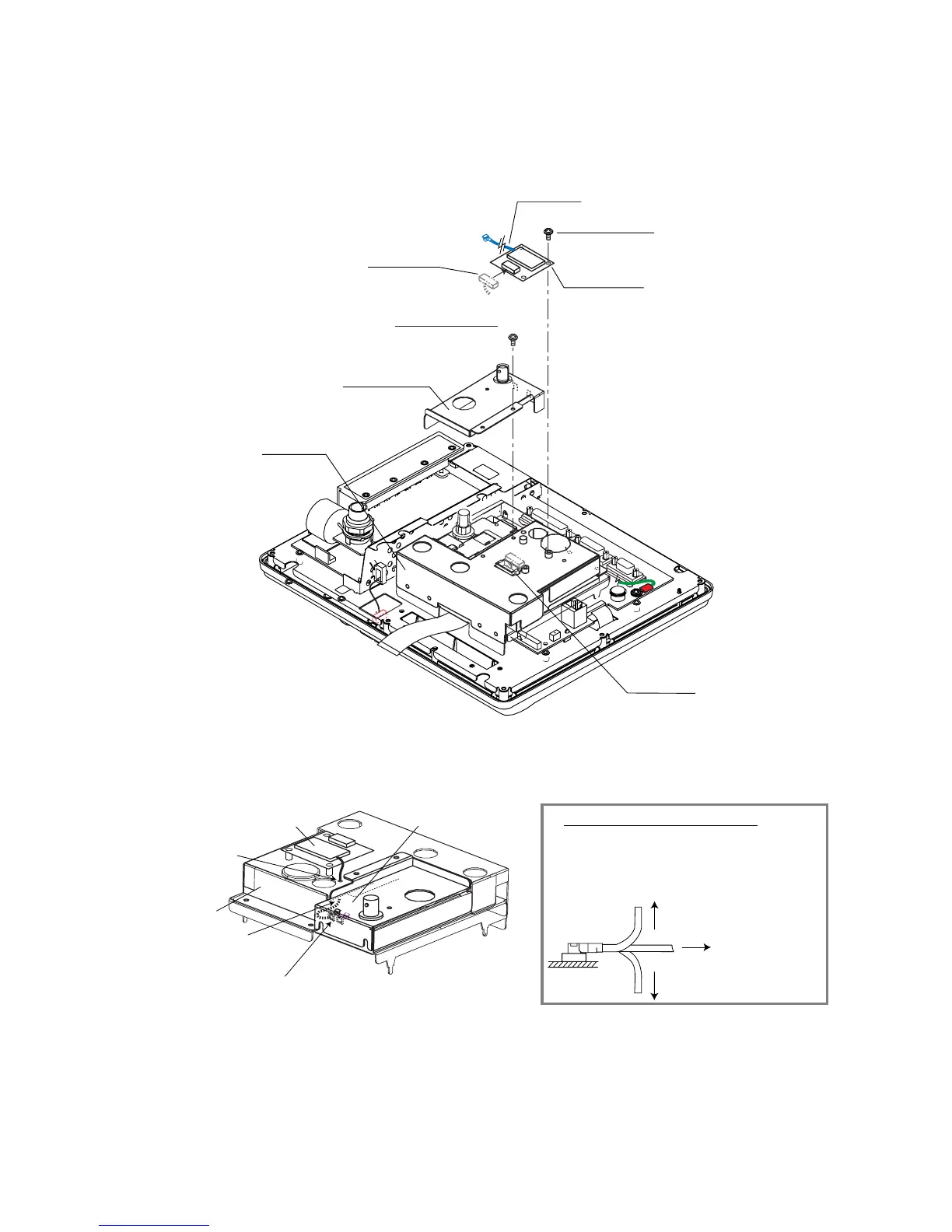
2. Unfasten four pan head screws (M3x8) to remove the RF cover (S).
3. Fasten three pan head screws (M3x8, supplied with the kit) to attach the GPS board to
the RF cover.
4. Attach the 7P connector from the RF cover to the JI on the GPS board.
J1
7P connector
GPS board
Cable
J1
Pan head screw
M3x8, 3 pcs.
Pan head screw
M3x8, 4 pcs.
(marked with "#")
RF cover (S)
RF cover
Grommet
#
#
#
#
Removing RF Cover (S)/Fixing GPS Board
5. Pass the cable from the GPS board through the hole on the RF cover, and then connect
it to J4 on the RF CON/CPU board.
GPS board
Pass the cable
through this hole.
RF cover
Pass the cable
under the RF cover.
Fix the cable with the clamp.
J4
RF CON/CPU board
1. Attach the connector at right angle.
If not, connector pins may be bent.
2. After connecting connector assemblies, the load
on their cables should be as below.
less than 2.94N (300gf)
less than 2.94N (300gf)
less than 9.8N (1kgf)
How to treat connectors
Fasten the cable at the clamp next to the J4 connector.
6. Remount the RF cover (S) using four pan head screws (M3x8) unfastened at step 2.
 Loading...