2-1
2.1 Overview
Outline
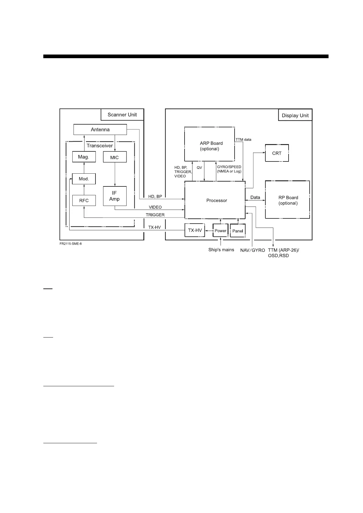
Figure 2.1 Simplified block diagram
TX
The trigger pulse from the SPU (Processor) Board is delivered to the MODULATOR Board
which outputs the signal to oscillate the magnetron, and then radar wave is emitted from the
radiator.
RX
The 9.4 GHz echo signal received by the antenna is converted to 60 MHz signal by the MIC,
amplified by IF Amplifier, and fed to the SPU (Processor) Board as a video signal. It is digitally
processed and then displayed on the CRT. The SPU Board contains a video amplifier.
Auto Plotter (optional)
The following signals are applied from the SPU Board to the ARP-26 Board: Heading, Bearing
pulse, Video, Trigger, Bearing in AD format, and Ship’s speed in IEC-61162. Target acquision
and tracking are performed on the ARP Board, and displayed on the CRT. Target data includes
target position, CPA, TCPA, Speed, and Course.
Plotter (optional)
Data such as latitude and longitude in IEC-61162 format is delivered from the SPU Board to the
RP Board. Plotter data generated on the RP board is output to the SPU Board and processed to
display them on the screen. The plotter menu is generated on the SPU Board.
Chapter 2. BLOCK DESCRIPTION

 Loading...