2-5
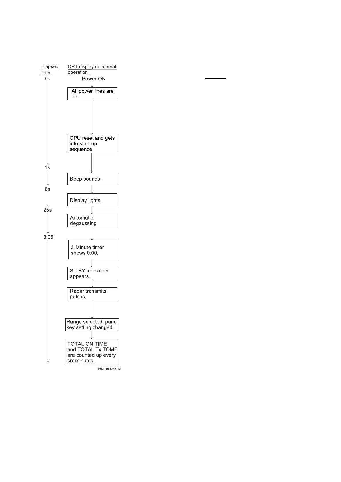
Start-up Sequence
Radar start-up sequence
Process
1.
The soft start circuit activates to protect the power ON/OFF
relay contacts.
2.
The input voltage monitor checks for abnormal voltage.
When ship’s mains is abnormal the ON/OFF relay trips off.
3.
The inverter comes on and outputs all line voltages. The
LED comes on and the inverter goes off when overcurrent
is detected.
4.
ROM, RAM, I/O port, custom IC, AGDC and VRAM are
initialized.
5.
The system is initialized using EEPROM and DIP switch
data.
6.
The timer starts counting down from 3 minutes (time
remaining for warm-up of magnetron).
7.
Checks for the absence/presence of a gyro signal.
8.
Checks for the absence/presence of the ARP and RP
Boards.
9.
The SPU Board starts operating.
Note) When H-sync signal is not applied to the CRT unit,
no HV is generated, resulting in nothing on the screen.
10.
The bearing scale, countdown indication, etc. appear.
11.
The screen is degaussed automatically.
3-minute warm-up can be skipped by pressing [ENTER]
several times while pressing and holding down [HL
OFF]. (Do not release this information to user.)
12.
Three-minute warm-up ends.
13.
The radar goes into stand-by.
14.
Checks for the presence of the BP (Bearing Pulse) signal.
15.
The tuning circuit goes into “short search mode.”
16.
When the range is changed, the tuning circuit goes into
“short search mode.”
17.
Panel settings are written onto the EEPROM.
18.
Time data are written onto the EEPROM.

 Loading...