1-1
1.1 Outline
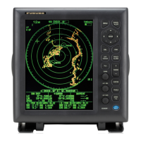
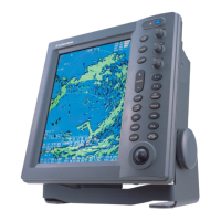
This manual provides the information necessary for the servicing and adjustment of the radars
FR-2115 and FR-2125.
The antenna unit uses a Log IF amplifier.
The features are;
6 pulselengths enabling echo size on the screen to be similar in all ranges
Flash ROM enabling program update to use a PC
Non-interlace, high-resolution display (1024x1280 dots)
New microprocessing technology with high-speed high-density gate array
Radar mapping capability
(Lines and Marks can be entered without the RP board, Gyro and L/L data required)
New cast aluminum scanner gearbox
New series of streamlined radiators, fixing feeder waveguide not required at installation
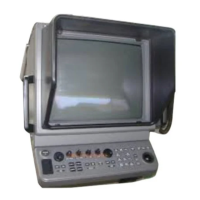
Display unit separable into Monitor, Control Unit, and Processor Units
Stabilized antenna rotation
Improved short-range performance using shorter pulselength and higher repetition rate than
before.
The table below shows the major specifications of each model.
Functions FR-2115 FR-2125
Maximum Range
72 NM(R-type)
96 NM(IMO type)
120 NM(R-type)
96 NM(IMO type)
Program Number
0359149-1XX
English
Japanese
Tuning Voltage
(displayed at manual tuning)
2.0 V to 32 V
RF Module RTR-062 RTR-063
Antenna Rotation 24 rpm or 42 rpm
Output Power 12 kW 25 kW
TX-HV Board HV-9017 A HV-9017 B
Input Voltage (Ship’s Mains)
24/32 VDC : 21.6 to 41.6 V
110 VAC : 90 to 126 V
220 VAC : 198 to 253 V
The major parts and P.C. Boards used in the display and scanner units are tabulated on the next
page.
Chapter 1. GENERAL
 Loading...