2-10
Auto Tuning Function
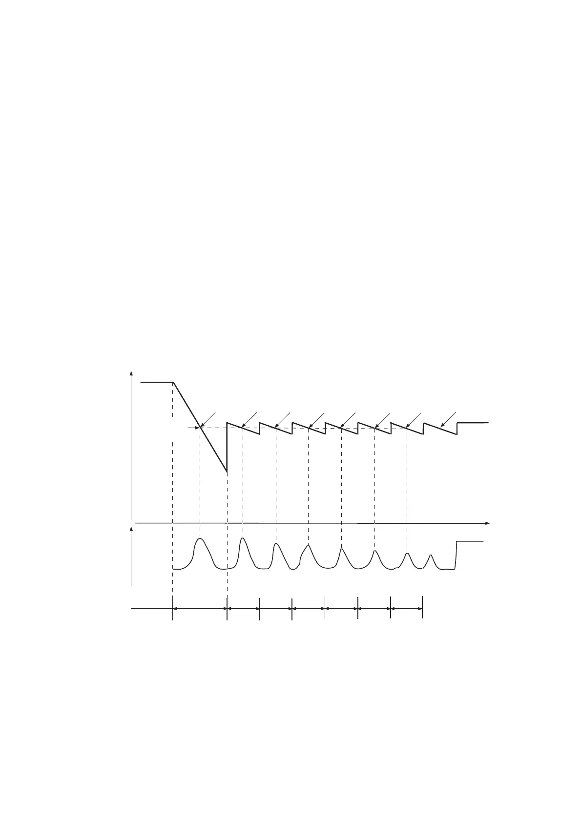
The system provides auto tuning mode which eliminates the adjustment of the receiver for
maximum echoes. The “Tune Initialization” is required after not only the installation but also the
replacement of RF unit, magnetron, MIC, and SPU board, so that the tune control voltages for
each pulse are memorized onto the EEPROM. The figure below illustrates how the tune
initialization takes place. First, full search is performed using a long pulse to find the tuning
point (a). Next, short search is performed using all pulses to find tuning points (b). After the
initialization, the pulselength used before the tune initialization is selected.
Full search: Varying tune control voltage (TUNE CONT) from about 5 V to 30 V, the
maximum tune indicator voltage is found and that tune control voltage (a) is
memorized.
Short search: The tune control voltage changes between the tune voltage (a) plus and minus
2.5 V for fine tuning.
When the radar is set from ST-BY to TX, short search is made twice. When the pulselength is
changed, short search is made once.
Figure 2.6 Tune Initialization
about 32 V
Tuning
control
voltage
about 2 V
(a)
(b)
Full
search
Short
search
Tracking
Time
LP
Tuning
indicator
voltage
Max. about 3 V
Min. about 1 V
FR2115-SME-14
(b)
(b)
(b)
(b)
(b)
LP M3
M2
M1
S2
S1
Pulselength
EEPROM
backup
Auto and
Man. coarse
tuning pt.
Max.
Tuning Ind.
voltage
Max.
Tuning Ind.
voltage
Pulse length in use
Auto coarse
tuning point
Max.
Tuning Ind.
voltage
Max.
Tuning Ind.
voltage
Max.
Tuning Ind.
voltage
Max.
Tuning Ind.
voltage
 Loading...